Inverter and vehicle drive unit using the same

a technology of inverter and drive unit, which is applied in the direction of electrical apparatus, semiconductor devices, semiconductor/solid-state device details, etc., can solve the problems of increasing the number of wires to be used, long work time, and increasing the time required for bonding of each wire, so as to improve the reliability of the inverter and improve the assembly capacity. , the effect of large curren

Active Publication Date: 2009-09-15
HITACHI ASTEMO LTD
View PDF13 Cites 33 Cited by
  • Summary
  • Abstract
  • Description
  • Claims
  • Application Information

AI Technical Summary

Benefits of technology

[0005]With respect of the bonding wires for connecting the switching device, to prevent the wires from fusion due to generation of heat by a current when the current amount controlled by the switching device is increased, it is necessary to increase the number of wires to be used for connection or increase the diameter of each wire.
[0007]Further, when bonding wires used are thickened and the time required for bonding is prolonged, the damage caused to the switching device during bonding is increased and a problem arises that the reliability is lowered.
[0008]An object of the present invention is to improve the assembly capacity of an inverter or a vehicle drive unit.
[0010]By use of such a constitution, the laminal conductor flowing a large current is connected to the electrode of the semiconductor device, thus they can be connected electrically, and compared with use of wire bonding, the assembly capacity is improved, and the reliability of the inverter is also improved.
[0011]According to the present invention, a large current can be realized and the assembly capacity can be improved.

Problems solved by technology

The wires illustrated here are thicker than wires generally used and a problem arises that the time required for bonding of each wire is long.
Further, the number of wires to be used is increased, thus the work time thereof becomes longer.
The time is explained above as an example, though not only in respect of time but also in respect of necessary machinery and technology, a big problem is imposed in the workability.
Further, when bonding wires used are thickened and the time required for bonding is prolonged, the damage caused to the switching device during bonding is increased and a problem arises that the reliability is lowered.

Method used


Image

  • Inverter and vehicle drive unit using the same
  • Inverter and vehicle drive unit using the same
  • Inverter and vehicle drive unit using the same

Examples


second embodiment

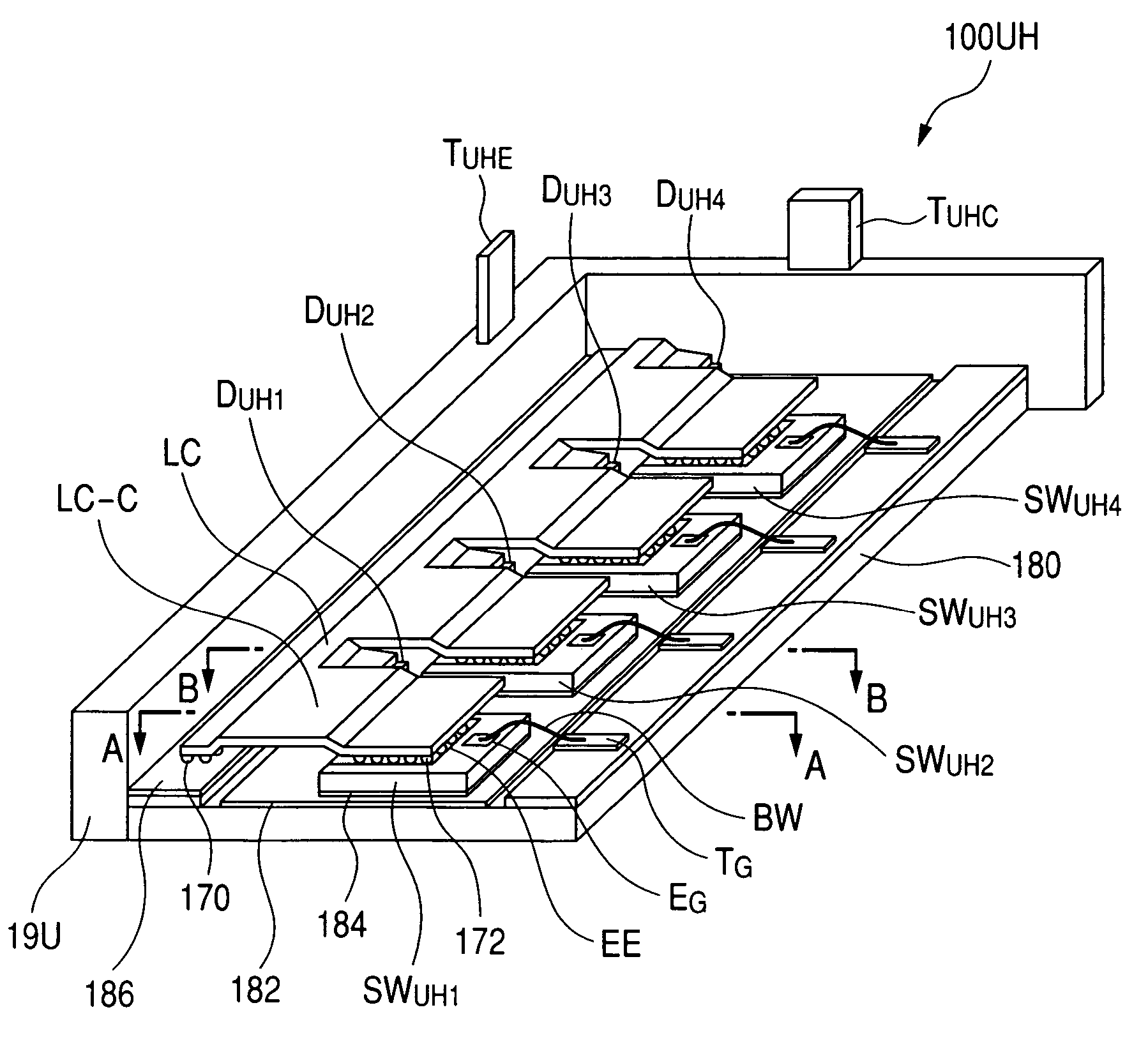
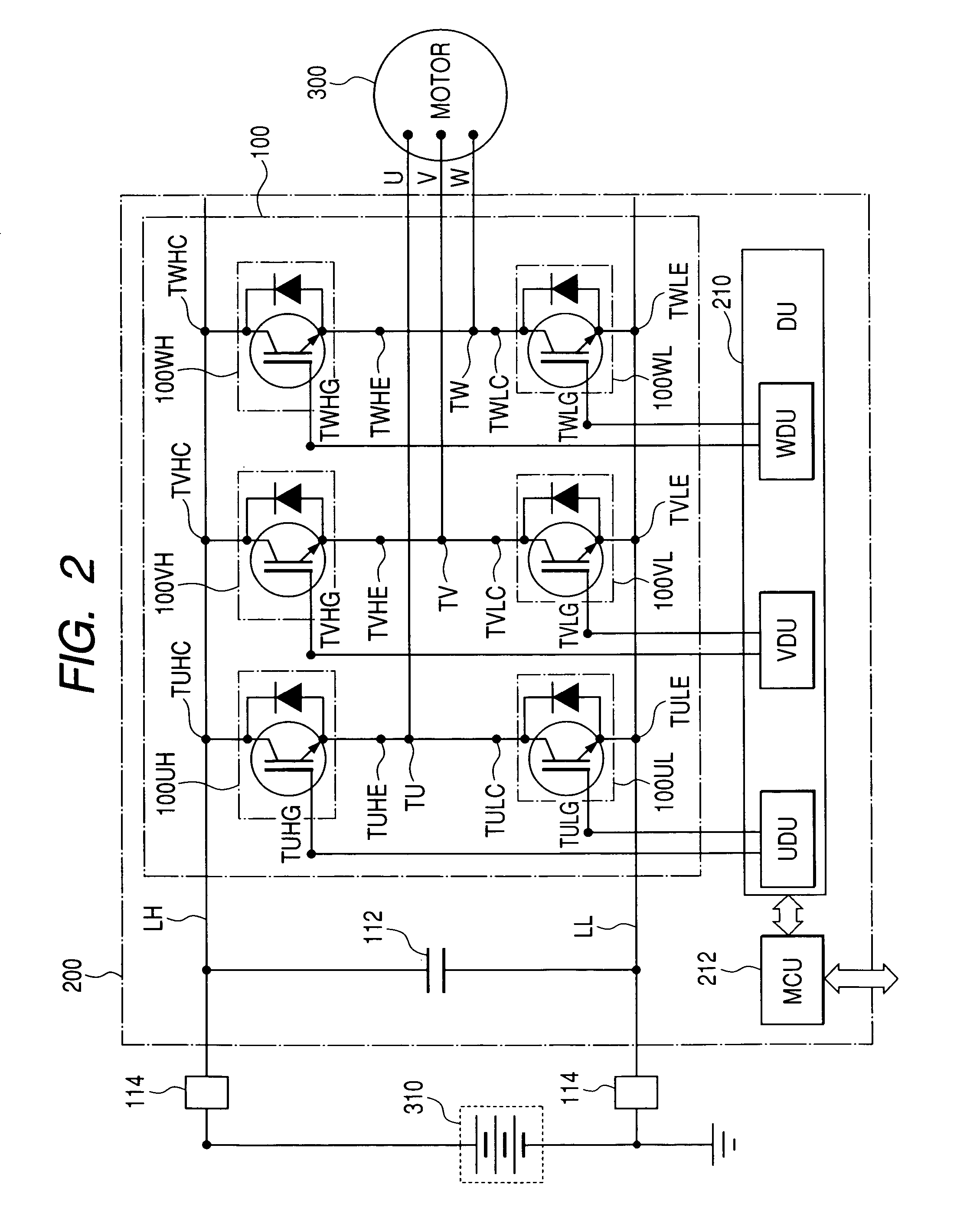
[0093]Next, by referring to FIG. 11, the constitution of the power module of the present invention will be explained. In this example, the power module is used in an inverter of a three-phase AC motor drive unit. The external constitution of the power module of this embodiment is the same as that shown in FIG. 4. Further, the circuit diagram of the power module of this embodiment is the same as that shown in FIGS. 2 and 3.

[0094]FIG. 11 is an enlarged view of the arm constitution of the power module of this embodiment. Here, an example of the module 100UH of the upper arm of the phase U will be explained, though the module constitutions of the other arms are the same. Further, the same numerals as those shown in the other drawings indicate the same parts.

[0095]In the arm 100UH-A, the switching device SWUH′ is arranged upside down for that shown in FIG. 5. Therefore, on the top side, the collector electrodes are positioned and on the bottom side, the emitter electrodes and gate electr...

third embodiment

[0098]Next, by referring to FIG. 12, the constitution of the power module of the present invention will be explained. In this example, the power module is used in an inverter of a three-phase AC motor drive unit. The external constitution of the power module of this embodiment is the same as that shown in FIG. 4. Further, the circuit diagram of the power module of this embodiment is the same as that shown in FIG. 2. FIG. 12 is an enlarged view of the arm module constitution of the power module of this embodiment. Here, an example of the module 100UH of the upper arm of the phase U will be explained, though the module constitutions of the other arms are the same. Further, the same numerals as those shown in the other drawings indicate the same parts.

[0099]In the arm module 100UH-B, the loading method of the switching device SWUH′ onto the insulating substrate 180, the shape of the lead-shaped conductor LC-A, and the connection method of each electrode by the solder bumps 172A, 172B, ...

fourth embodiment

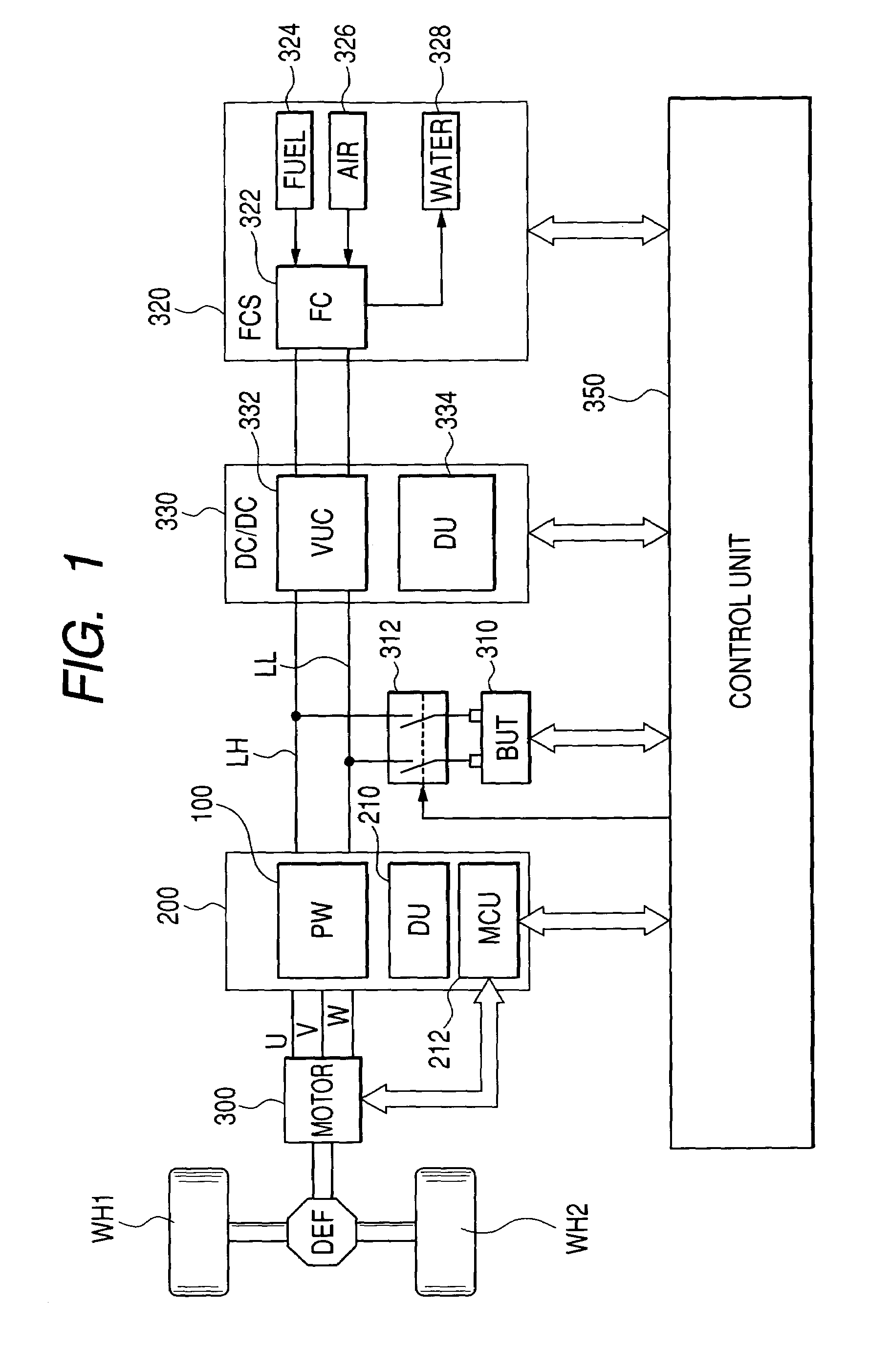
[0102]Next, by referring to FIG. 13, the constitution of the power module of the present invention will be explained. In this example, the power module is used in an inverter of a three-phase AC motor drive unit. The external constitution of the power module of this embodiment is the same as that shown in FIG. 4. Further, the circuit diagram of the power module of this embodiment is the same as that shown in FIG. 2.

[0103]FIG. 13 is a cross sectional view of the arm module of the power module of the fourth embodiment of the present invention. The drawing shows the sectional structure equivalent to the section A-A shown in FIG. 5. Further, the same numerals as those shown in the other drawings indicate the same parts.

[0104]The lead-shaped conductor LC-B uses a core of copper and on the joined parts of the switching device SWUH′ and the intra-case terminal 186, projections 172D and 170A integrally formed with the terminals of the lead-shaped conductor LC-B are formed. The projections 1...


PUM


Abstract

The inverter has a plurality of arms for conducting or cutting off a current and each arm has a switching device and a first and a second wiring layer for connecting the switching device. The first and second wiring layers of each arm are respectively formed on insulating substrates, and one face of the switching device is fixed to the first wiring layer, and the second wiring layer and the other face of the switching device are electrically connected by a laminal conductor, and the laminal conductor has a first and a second connection, and the first connection of the laminal conductor is fixed to the other face of the switching device, and the second connection of the laminal conductor is fixed to the second wiring layer.Thereby, a large current of the inverter can be realized and the assembly capacity of the inverter or the vehicle drive unit will be improved.

Description

CLAIM OF PRIORITY[0001]The present application claims priority from Japanese application serial no. 2004-291002, filed on Oct. 4, 2004, the content of which is hereby incorporated by reference into this application.FIELD OF THE INVENTION[0002]The present invention relates to an inverter and a vehicle drive unit using it.BACKGROUND OF THE INVENTION[0003]Conventionally, in an electric car driven only by a motor and a hybrid electric car driven by both an engine and a motor, a direct current supplied from a DC power source is converted to an alternating current supplied to a vehicle drive motor by an inverter. The inverter, for example, as described in Japanese Patent Laid-Open No. 2001-258267 and Japanese Patent Laid-Open No. 2002-369550, is composed of a semiconductor apparatus called a power module or an inverter bridge circuit and a control substrate loading electronic parts such as a capacitor, a drive circuit, an interface circuit, a sensor circuit, a calculator, and a control po...

Claims


Application Information

Patent Timeline
Patent Type & Authority Patents(United States)
IPC IPC(8): H01L23/495H01L23/48H02M7/48
CPCH01L24/36H01L24/40H01L24/84H01L24/91H01L24/95H01L25/072H02M7/003H01L2224/48091H01L2224/48472H01L2924/01004H01L2924/01013H01L2924/01027H01L2924/01029H01L2924/0103H01L2924/01033H01L2924/01047H01L2924/01049H01L2924/01051H01L2924/01074H01L2924/01078H01L2924/01079H01L2924/01082H01L2924/13055H01L2924/13091H01L2924/19041H01L2924/19043H01L2924/30107H01L2924/3011H01L2924/01005H01L2924/01006H01L2924/01019H01L2924/01023H01L2924/014H01L2224/45124H01L2224/45147H01L2224/73265H01L2924/10253H01L2224/16245H01L2224/73221H01L2224/37124H01L2224/37147H01L2224/37655H01L2224/37644H01L2224/37611H01L2924/1306H01L2924/1301H01L2924/1305H01L2924/00014H01L2924/00H01L2924/01026H01L2924/01028H01L2924/351H01L2224/40137H01L2224/40095H01L2224/40225H01L24/37H01L2224/4007H01L2924/00011H01L2224/84801H01L2224/83801H01L2224/84345H01L2224/0401
Inventor HOZOJI, HIROSHIMORITA, TOSHIAKISHIGETA, SATORUSUWA, TOKIHITO
Owner HITACHI ASTEMO LTD
Why Eureka
Try Eureka