Automated sample analysis system and method

Active Publication Date: 2009-09-29
NEXUS BIOSYSTEMS INC
View PDF35 Cites 14 Cited by
  • Summary
  • Abstract
  • Description
  • Claims
  • Application Information

AI Technical Summary

Benefits of technology

[0016]The illumination sources can be xenon flash tubes and the processor can control the duration of the flash. A capacitor or capacitor bank can provide the energy for the flash tubes. A Silicon Controlled Rectifier (SCR) or thyristor can connect the capacitor to the flash tube. The processor can control conduction through the SCR, and thus, energization of the flash tubes. The processor can also interrupt the flow of current through the SCR to control the illumination, or intensity of light.
[0017]In another aspect of the invention, a shelf or storage location for the multi-well plates includes locating members for accommodating a plurality of multi-well plate sizes. The shelf is configured to store one multi-well plate from a plurality of multi-well plate sizes. The shelf can be an individual shelf that can be conne

Problems solved by technology

However, the amount of laboratory space is limited and it is desirable for an automated system to occupy minimal laboratory space.
The need for a refrigerated room expands the amount of laboratory space that needs to be dedicated to protein crystallization and conversely, reduces the amount of laboratory space available for other experiments.
Other problems associated with manually examining each sample well include low throughput and high susceptibility to sample damage due to handling.
A technician is unable to process thousands o

Method used


Image

  • Automated sample analysis system and method
  • Automated sample analysis system and method
  • Automated sample analysis system and method

Examples


Embodiment Construction

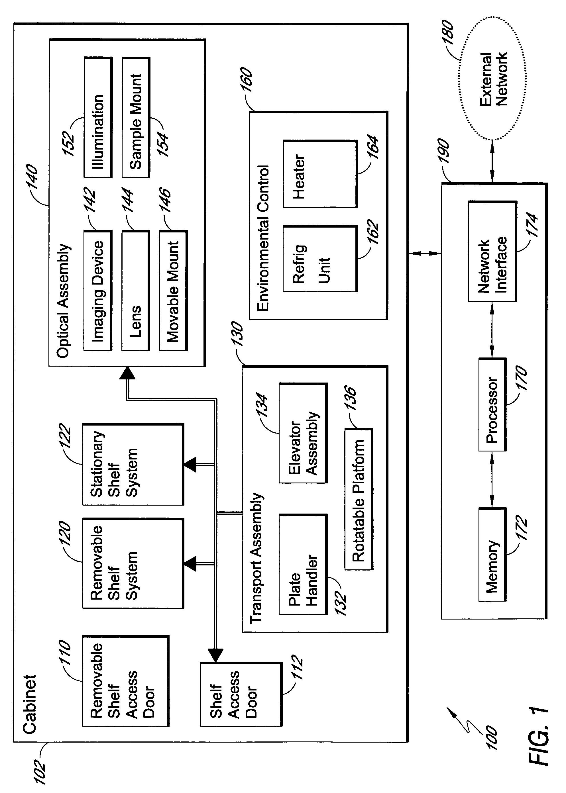
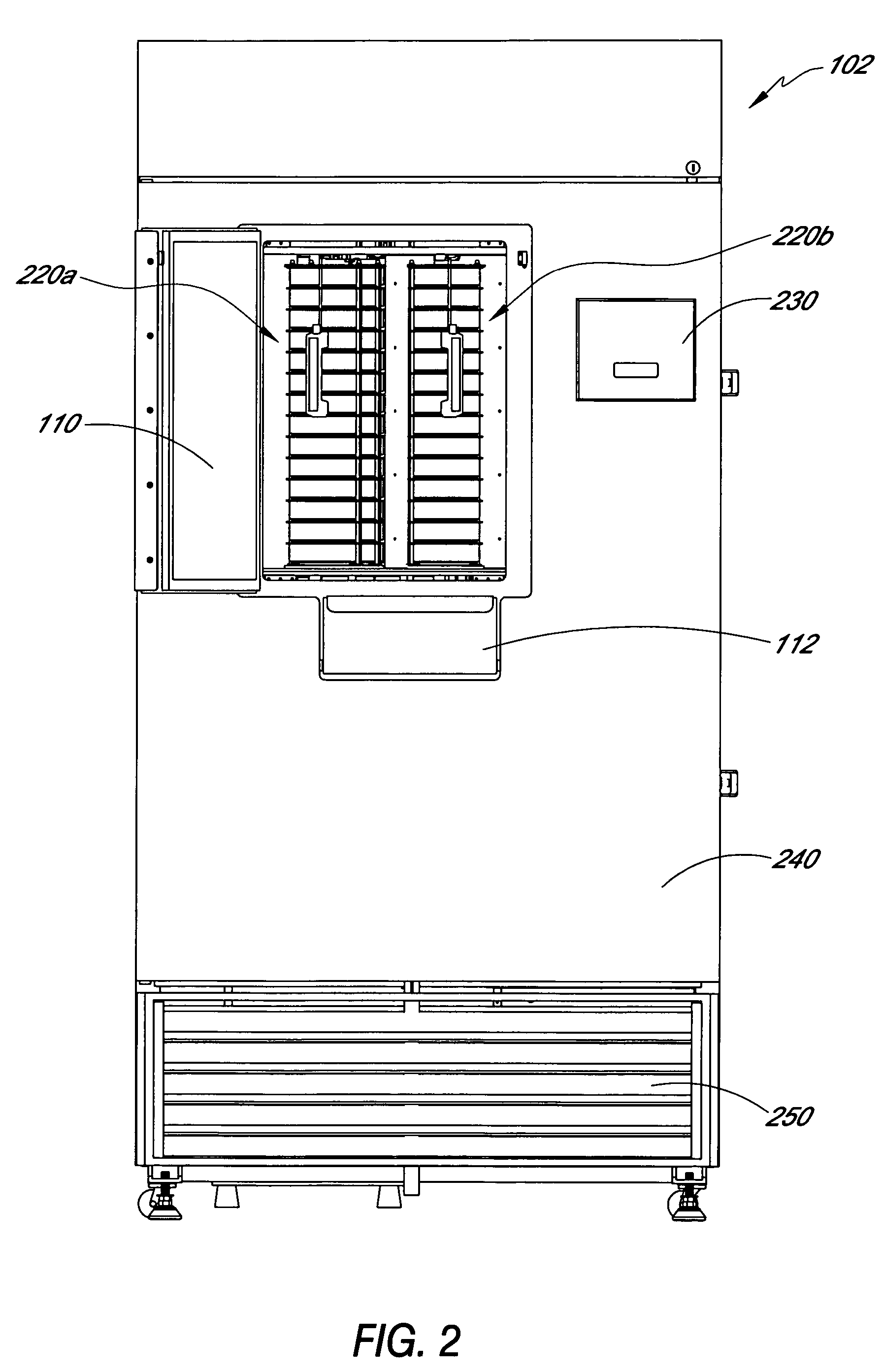
[0038]FIG. 1 is a functional block diagram of one embodiment of an automated sample analysis system 100. The automated sample analysis system 100 includes a cabinet 102 including a removable shelf access door 110 and a shelf access door 112 that are typically mounted on a front of the cabinet 102 and provide access to an environmentally controlled chamber within the cabinet 102. The environmentally controlled chamber of the cabinet 102 can also be referred to as the interior of the cabinet 102.

[0039]The cabinet 102 also includes spaces that are external to the environmentally controlled chamber. For example, the cabinet 102 includes an environmental control unit 160 mounted external to the environmentally controlled chamber. The environmental control unit includes a refrigeration unit 162 and a heater 164.

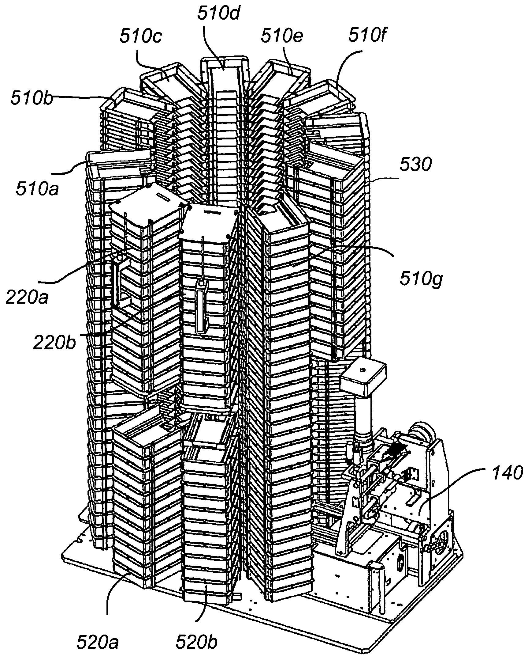
[0040]The cabinet 102 houses a removable shelf system 120, a stationary shelf system 122, a transport assembly 130 and an optical assembly 140 within the environmentally controlled...


PUM


Abstract

An automated biological sample analysis system and method for use in incubating and analyzing multiple samples for protein crystallization. A temperature controlled cabinet houses sample storage, sample transport, and sample imaging systems. The operation of the system is automated and can be controlled by software, which can be reconfigured remotely. An array of storage shelves includes multiple shelf columns arranged around a core. Multiple banks of removable shelves arranged as magazines are accessed through a door on the cabinet. Each shelf stores a multi-well plate and different sizes can be stored in different shelves. The core houses a sample transport system that includes a multi-axis robot that rotates about a vertical axis to access the shelves in the shelf array. The transport system retrieves and replaces the multi-well plates in the shelves and can move plates from the shelves to an imaging system where each sample can be automatically imaged.

Description

RELATED APPLICATIONS[0001]This application claims priority to U.S. Provisional Patent Application No. 60 / 444,519, titled “AUTOMATED SAMPLE ANALYSIS SYSTEM AND METHOD,” filed on Jan. 31, 2003, Provisional Patent Application No. 60 / 444,585, titled “REMOTE CONTROL OF AUTOMATED LABS,” filed on Jan. 31, 2003, U.S. Provisional Patent Application No. 60 / 444,586, titled “AUTOMATED IMAGING SYSTEM AND METHOD,” filed on Jan. 31, 2003, and Provisional Patent Application No. 60 / 474,989, titled “IMAGE ANALYSIS SYSTEM AND METHOD,” filed on May 30, 2003, each of which is hereby incorporated by reference for all purposes.BACKGROUND OF THE INVENTION[0002]1. Field of the Invention[0003]The invention relates to the field of sample analysis. More particularly, the invention relates to an automated biological sample analysis system.[0004]2. Description of the Related Art[0005]Modern chemistry and biology laboratories produce and analyze multiple samples concurrently in order to accelerate the development...

Claims


Application Information

Patent Timeline
IPC IPC(8): G06K9/00A47B88/06A61B19/02A61C19/02B01L9/02A47B88/48B01L9/00C30B7/00C30B29/58G01N1/40G01N15/14G01N21/25G01N35/00G01N35/02G01N35/04G02B21/00
CPCG02B21/0016C30B29/58G01N21/253G01N35/028C30B7/00B01L9/523G01N15/1475G01N35/0099G01N2001/4027G01N2015/1493G01N2035/00356G01N2035/00455G01N2035/00881G01N2035/042G01N2035/0425G01N2035/0463
Inventor AFFLECK, RHETT L.BODNAR, MIKELEVIN, ROBERT K.LILLIG, JOHN E.NEEPER, ROBERT K.
Owner NEXUS BIOSYSTEMS INC
Why Eureka
Try Eureka