High density low pressure plasma sprayed focal tracks for X-ray anodes

a low-pressure plasma and focal track technology, applied in the field of medical diagnostic equipment, can solve the problems lowering the velocity, and failing to duplicate the results of those skilled in the art, and achieve the effect of reducing the pressure of the vacuum chamber

Inactive Publication Date: 2009-10-13
SURFACE MODIFICATION SYST
View PDF14 Cites 35 Cited by
  • Summary
  • Abstract
  • Description
  • Claims
  • Application Information

AI Technical Summary

Benefits of technology

[0040]the turntable is comprised of an insulating platform allowing the base to rest thereon, and preventing heat conduction from the anode into the turntable; and
[0081]placing the formed anode within a vacuum chamber and reducing a pressure of the vacuum chamber to de-gas the formed anode, and commencing a heat treatment process of the formed anode therein within the vacuum chamber, which allows the void pores therein the focal track to consolidate.

Problems solved by technology

However, attempts to duplicate results by those skilled in the art have not been successful, especially for larger diameter anodes.
In other words, the higher chamber pressures increased the drag forces on the tungsten particles, which lowered their velocity, which in turn, lowered their packing density in forming the focal track structure.
The use of particles with large mass differences between particle sizes bring about another disadvantage.
This large differences in particle sizes of the tungsten or tungsten alloy particles cause wide range of thermal histories and velocities between each particle, which lead to structures having multitude of defects such as re-solidified and un-melted particles entrapped between splats, which result in high levels of porosity of the focal track.
Accordingly, in spite of intensive development efforts around the world in recent years, the focal track coatings using conventional plasma spraying taught by the U.S. Pat. No. 4,534,993 to Magendans et al. has not be successful.
One of the deficiencies of the U.S. Pat. No. 6,132,812 to Rodhammer et al. is that it has a low feed rate of the tungsten or tungsten alloy particles, which leads to higher process or production time.
However, slow rotational rates for larger diameter targets will lead to conductive and irradiative losses of heat.
That is, as one section of the target is heated while the target slowly rotates, the diagonally opposite section of the same away from the heat source cools, and hence, for larger targets slow rotation of the target will not function to allow even or uniform temperature for the entire target.
A further disadvantage with Rodhammer et al. is the use of columnar grain structure.
The columnar grain structures have a possibility of longer cracks along columnar grain boundaries.
Regrettably, both the U.S. Pat. No. 4,534,993 to Magendans et al. and the U.S. Pat. No. 6,132,812 to Rodhammer et al. lack the teaching and method for maintaining a substantially uniform temperature for the recently developed larger diameter anode bodies.
Unfortunately, most prior art conventional plasma spraying methods of manufacturing a rotary anode for x-ray tubes suffer from obvious disadvantages, one non-limiting example of which is in terms of thermal management of the application of materials that produce a focal track of the anode.

Method used


Image

  • High density low pressure plasma sprayed focal tracks for X-ray anodes
  • High density low pressure plasma sprayed focal tracks for X-ray anodes
  • High density low pressure plasma sprayed focal tracks for X-ray anodes

Examples


example 1

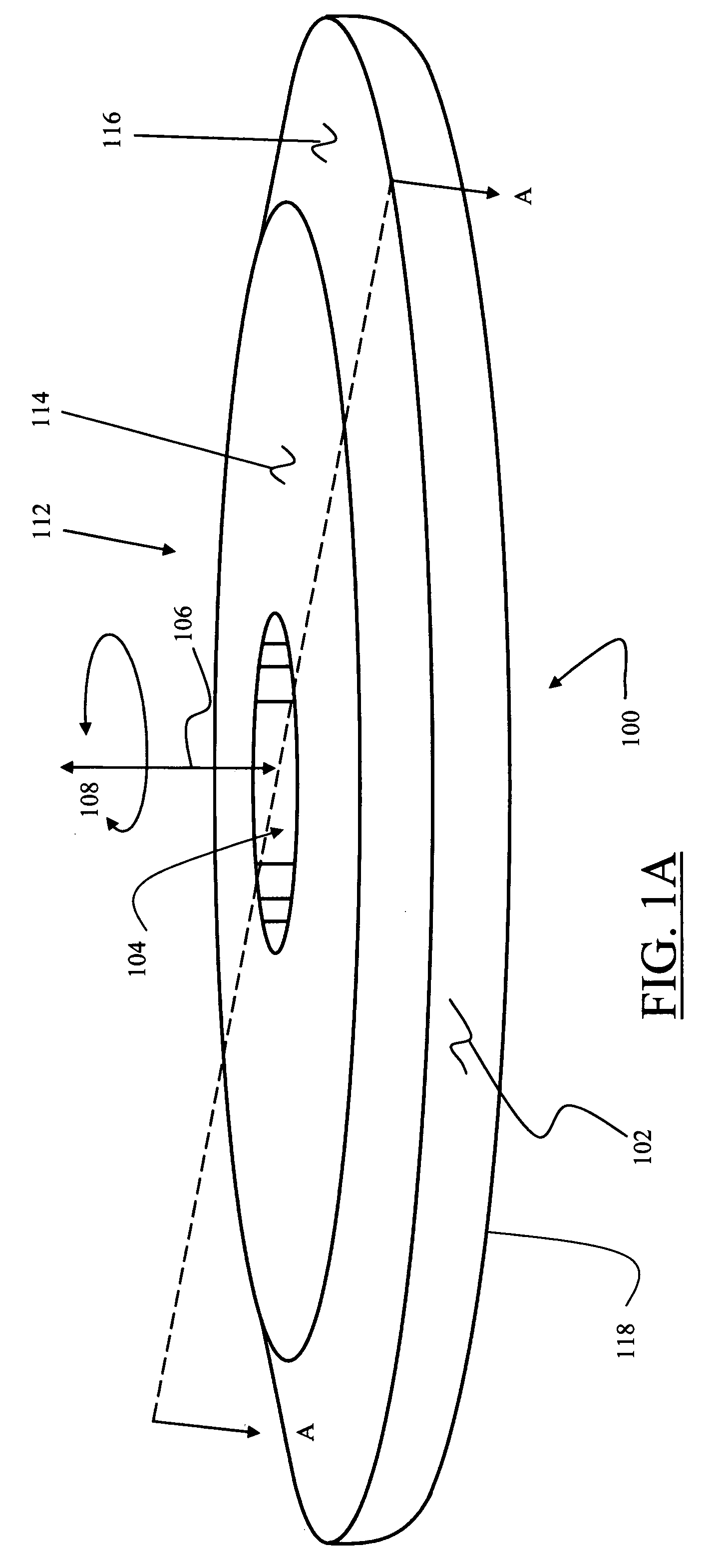
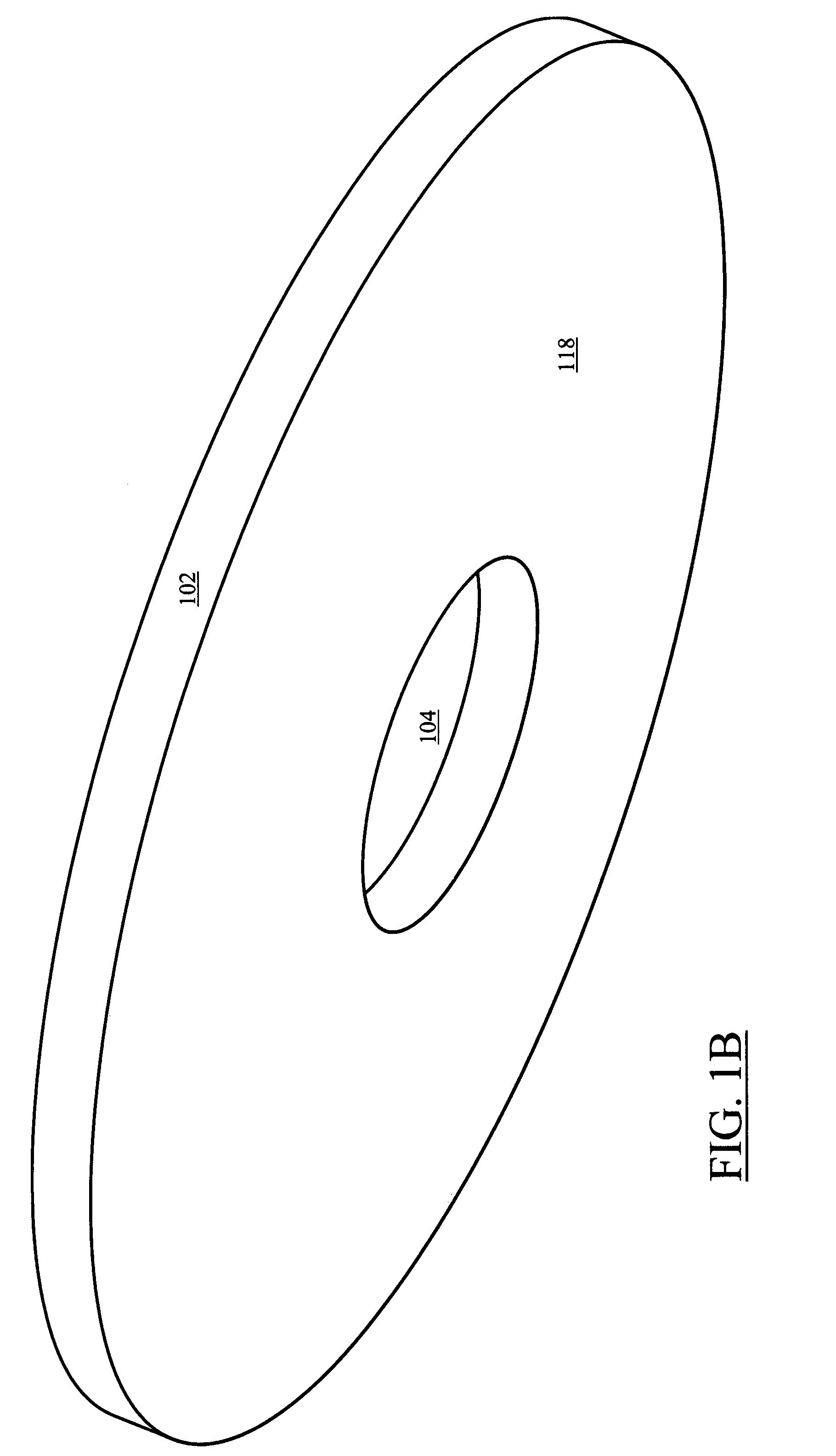
[0219]Base 100 used was a 4″¾″ thick TZM disc[0220]First lowering of pressure at 400 micron vacuum[0221]Backfill with argon to 30 Torr[0222]Negative Transferred Arc Sputter Clean at 10″ 2 KW[0223]Heat disc to above 1400° C.[0224]Deposit Tungsten 5% Rhenium Powder at 43 gr / min[0225]Helium 200 psi at 300 SCFH[0226]Argon 150 psi at 200 SCFH (functional acts 310 and 320 of FIG. 3)[0227]Plasma arc power of 100-112 KW[0228]Total Time of coating cycle 7 minutes[0229]Total thickness of focal track 0.052″

The coating structure is shown in FIG. 27. An equiaxed structure with a grain size of 10-20 microns was generated. The density of the coating measured using Archimedes technique is 96.5% of theoretical heat treatment in vacuum at 1600° C. for approximately 1-4 hours lead to densities of 97.5% without altering substantially the grain size.

example 2

[0230]Base used was 8″ TZM disc ¾″ thick[0231]Coating material Tungsten 10% Rhenium

Similar parameters as example 1 were used with the exception that the substrate temperature during deposition was maintained at 1200° C. and the deposition time was extended to 17 minutes to accommodate the larger area to be coated. The coating structure obtained is that of FIG. 26 which shows partial recystallization of the coating particles as they form the coating. The piece was heat treated at 1700° C. for approximately 4 hours and Hot Isostatic Pressed (HIP) at 28,000 psi, 1800° C. for about 4 hours. The resulting structure after heat treatment at 1700° C. is shown in FIG. 28. The after heat treat the grains were equiaxed and measured from 10-20 microns. The structure after HIP is shown in FIG. 29. The equiaxed grains measured from between 20-45 microns. The density of the HIPPED structure was found to be at a 98.5% minimum.


PUM

PropertyMeasurementUnit
particle sizeaaaaaaaaaa
pressureaaaaaaaaaa

Abstract

This invention involves the application of dense, metallurgically bonded deposits of tungsten and tungsten rhenium coatings onto preformed based x-ray anodes to be used as focal tracks. The coatings are applied by low pressure DC plasma spraying. The invention also includes heat treatments that further densify the as-applied coatings improving their suitability for use as focal tracks.

Description

CROSS-REFERENCE TO RELATED APPLICATIONS[0001]This Application claims the benefit of priority of prior U.S. Utility Provisional Patent Application No. 60 / 898,800, with a filing date of 31 Jan. 2007, the entire disclosure of which Application is expressly incorporated by reference in entirety herein.BACKGROUND OF THE INVENTION[0002](1) Field of the Invention[0003]The present invention relates to medical diagnostic equipment and, more particularly, to a method for manufacture of a rotary anode for X-ray tubes using high-density low-pressure plasma sprayed focal track for X-ray anodes, and the rotary anode produced.[0004](2) Description of Related Art[0005]Conventional methods or processes of manufacturing a rotary anode for x-ray tubes and the anode produced are well known. For example, the U.S. Pat. No. 4,534,993 to Magendans et al. teaches a conventional method or process of manufacturing a rotary anode for x-ray tubes and the anode produced using conventional plasma spraying of coat...

Claims


Application Information

Patent Timeline
Patent Type & Authority Patents(United States)
IPC IPC(8): H05H1/24
CPCC23C4/005C23C4/02C23C4/08H01J35/10C23C4/127H01J2235/1204H01J2235/081H01J2235/083C23C4/01C23C4/134
Inventor BAMOLA, RAJANSICKINGER, ALBERT
Owner SURFACE MODIFICATION SYST
Why Eureka
Try Eureka