Decoding unit and preprocessing unit implemented according to low density parity check code system
a parity check and code system technology, applied in the field of decoding units, can solve the problems of increasing the processing time, unable to show hardware implementation for specifically performing a huge amount of calculations, and requiring a long time and increase in unit scale to operate the gallager function, so as to reduce the complexity of construction
- Summary
- Abstract
- Description
- Claims
- Application Information
AI Technical Summary
Benefits of technology
Problems solved by technology
Method used
Image
Examples
first embodiment
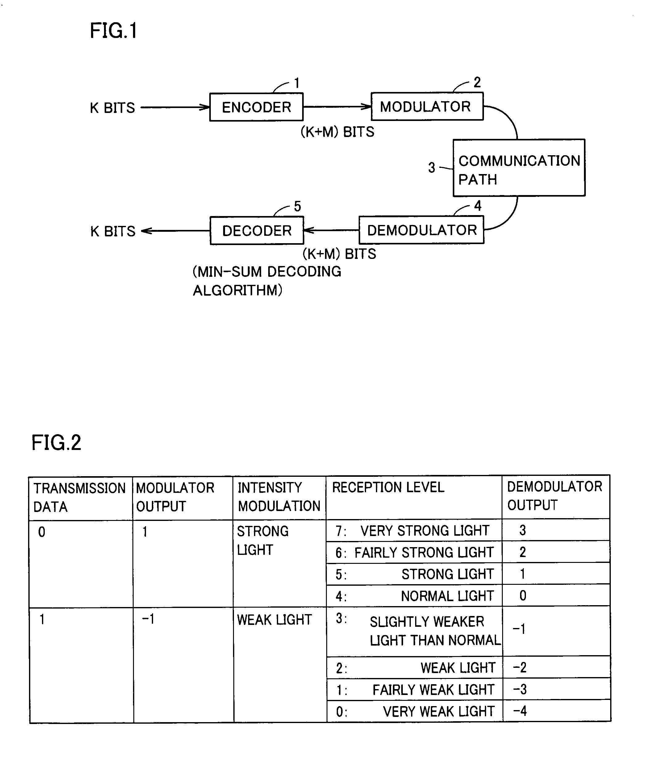
[0037]FIG. 1 shows an example of a construction of a communication system using a decoding unit according to the invention. In FIG. 1, the communication system includes, on a transmission side, an encoder 1 for producing transmission codes by adding redundancy bits for error correction to transmission information, and a modulator 2 for modulating a code of (K+M) bits received from encoder 1 in accordance with a predetermined method, and supplying the modulated codes to a communication path 3.
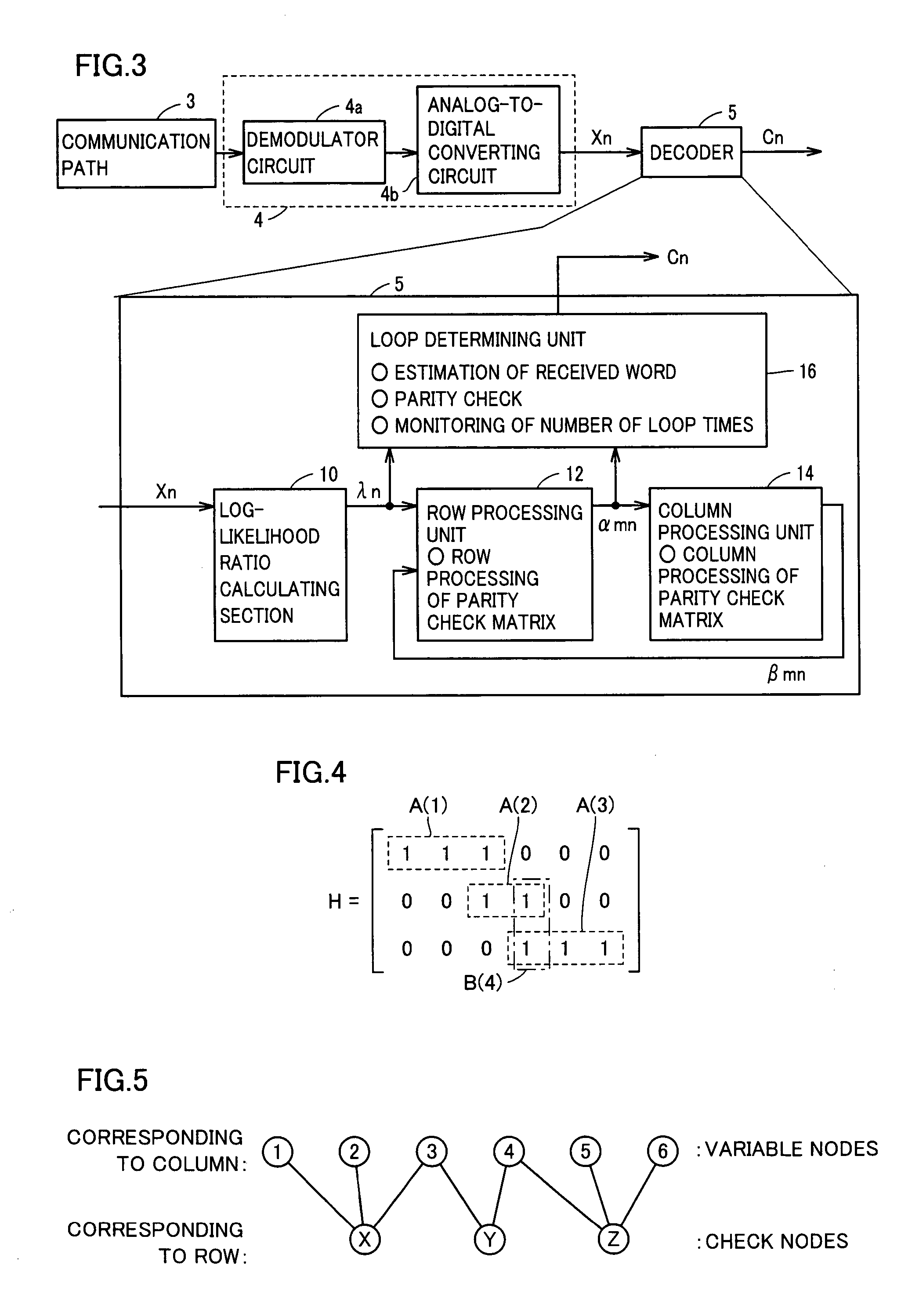
[0038]Encoder 1 adds redundancy bits of M bits for parity calculation to information of K bits, to produce an LDPC code (Low Density Parity Check code) of (K+M) bits. In a parity check matrix, a row corresponds to the redundancy bits, and a column corresponds to the code bits.
[0039]Modulator 2 performs modulation such as amplitude modulation, phase modulation, code modulation, frequency modulation or orthogonal frequency division multiplex modulation depending on the architecture of communicatio...
second embodiment
[0111]FIG. 13 schematically shows a construction of a Min operation unit according to a second embodiment of the invention. In FIG. 13, the Min operation unit includes first and second minimum value storages 22 and 24 using input values (λn+βmn) and storing the first and second minimum values among the absolute values thereof, respectively, a minimum position storage 40 for storing positional information POS in the processing unit for row processing of the first minimum value stored in first minimum value storage 22, and a selector 42 for selecting one of the first and second minimum values FIM and SEM based on comparison between positional information POS of minimum position storage 40 and positional information i of the signal of interest, i.e. the signal to be operated, and outputting an Min operation result MIN.
[0112]According to the construction of the Min operation unit shown in FIG. 13, it is merely required to store the position information in the row processing unit of firs...
third embodiment
[0124]Referring to FIG. 17, a check matrix of 6 rows by 12 columns will now be considered. The Min operation is effected on input signals X(1) to X(12). In the check matrix shown in FIG. 17, “1” is set in the first row on the 1st, 4th, 6th, 8th, 10th and 11th columns. In executing the Min operation in the processing of the 1st row, the first and second minimum values are detected from among input signals X(1), X(4), X(6), X(8), X(10) and X(11) on these columns, and are held. This detection of the minimum values can be performed in either a manner of detecting the minimum values by successively and sequentially accepting the input signals or a manner of processing the input signals in parallel, as will be described in the below in the order.
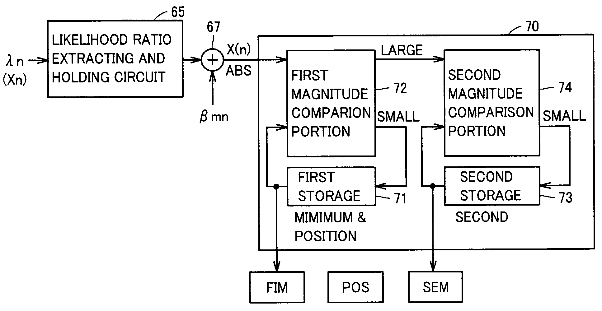
[0125]FIG. 18 schematically shows a construction of a Min operation section according to a third embodiment of the invention. Referring to FIG. 18, a preprocessing circuitry for the Min operation includes a likelihood ratio extracting and holding ...
PUM
 Abstract
Description
Claims
Application Information
 - R&D
- Intellectual Property
- Life Sciences
- Materials
- Tech Scout
- Unparalleled Data Quality
- Higher Quality Content
- 60% Fewer Hallucinations
Browse by: Latest US Patents, China's latest patents, Technical Efficacy Thesaurus, Application Domain, Technology Topic, Popular Technical Reports.
© 2025 PatSnap. All rights reserved.Legal|Privacy policy|Modern Slavery Act Transparency Statement|Sitemap|About US| Contact US: help@patsnap.com


