Fiber film reactors to effect separation and reaction between two immiscible reaction components

a fiber film reactor and reaction component technology, applied in the field of fiber reactors/contactors, can solve the problems of ptc project, most difficult to meet, and inability to use ptc technology,

Active Publication Date: 2009-11-17
CHEMTOR LP
View PDF19 Cites 27 Cited by
  • Summary
  • Abstract
  • Description
  • Claims
  • Application Information

AI Technical Summary

Benefits of technology

[0014]In an embodiment of the present invention is provided a process for conducting chemical reactions in a conduit reactor comprising introducing streams containing reactive species proximate an upstream end of a plurality of fibers positioned longitudinally within the conduit reactor, wherein a first stream constitutes a phase substantially constrained to the surface of the fibers and a second stream constitutes a substantially continuous phase that is in contact with and is substantially immiscible with the first stream, and whereby the reactive species in the constrained phase and the reactive species of the continuous phase interact to form at least one new chemical species. A phase transfer catalyst is employed to facilitate mass transfer. In an embodiment, a collection vessel can be provided for receiving the constrained phase and the continuous phase, wherein the constrained phase comprises a layer in a first portion of the collection vessel and the continuous phase comprises a layer in a second portion in the collection vessel, and the layer comprising the continuous phase and the layer comprising the constrained phase are separately withdrawn from the collection vessel. In additional embodiments of the present invention, the reaction process may include co-solvents to increase solubility of chemical species produced by the process.

Problems solved by technology

Despite these great benefits and the wide scope of applications, many chemical companies are still not using PTC technology.
Probably the most difficult challenge to be met in the development stage of a PTC project is separation.
Specifically, separation of phases can be difficult and time consuming since PTC catalysts resemble soaps and are interfacially active, and separation of catalysts after the reaction takes place is needed for product purity and quality.

Method used


Image

  • Fiber film reactors to effect separation and reaction between two immiscible reaction components
  • Fiber film reactors to effect separation and reaction between two immiscible reaction components
  • Fiber film reactors to effect separation and reaction between two immiscible reaction components

Examples


example 1

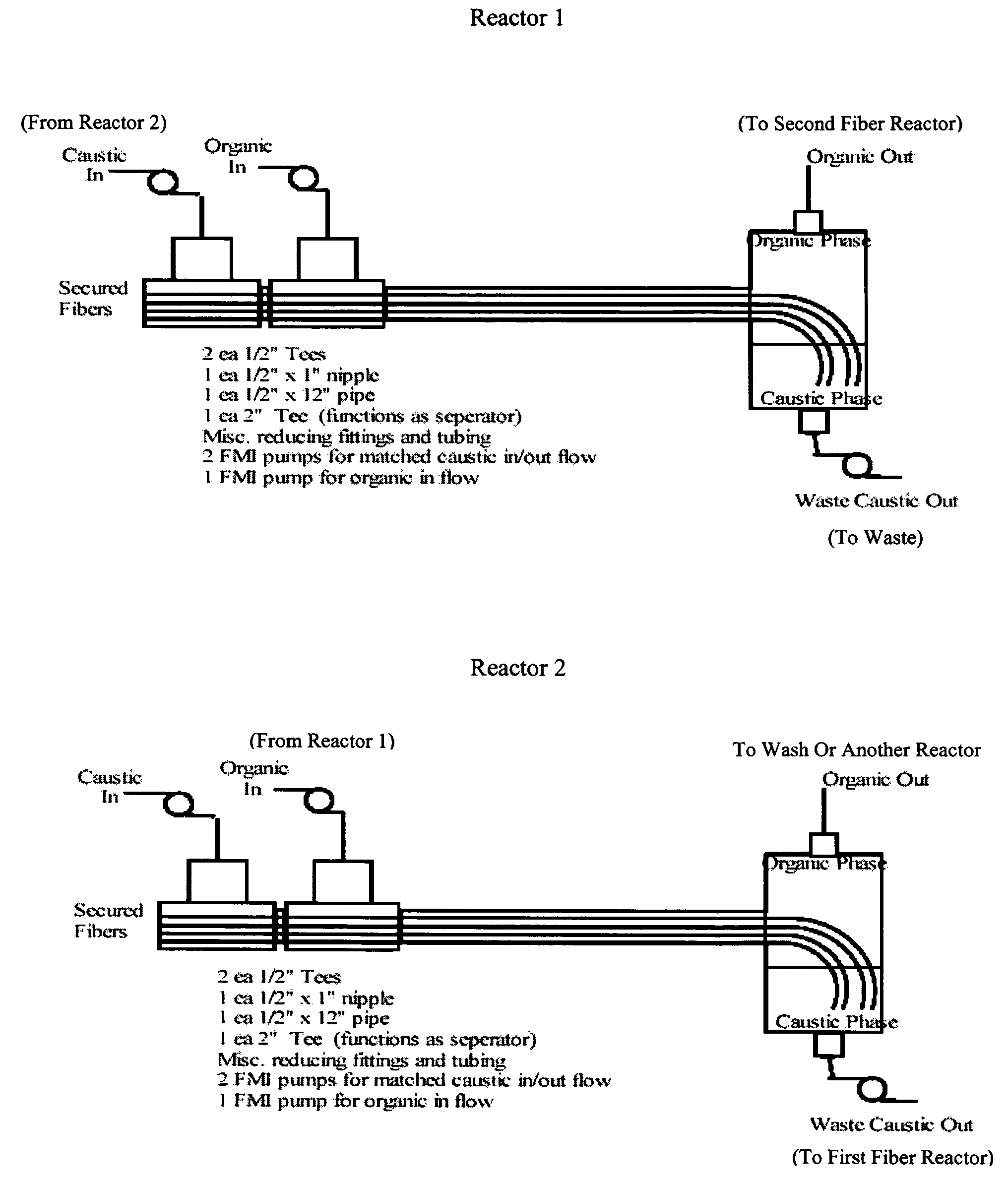
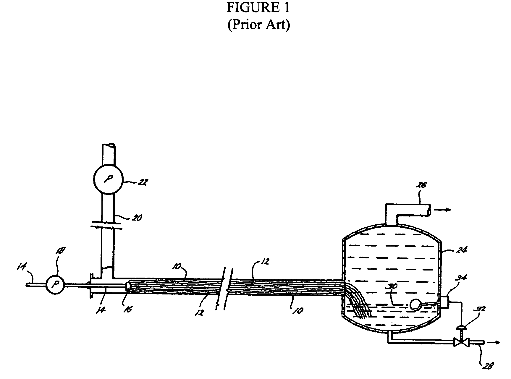
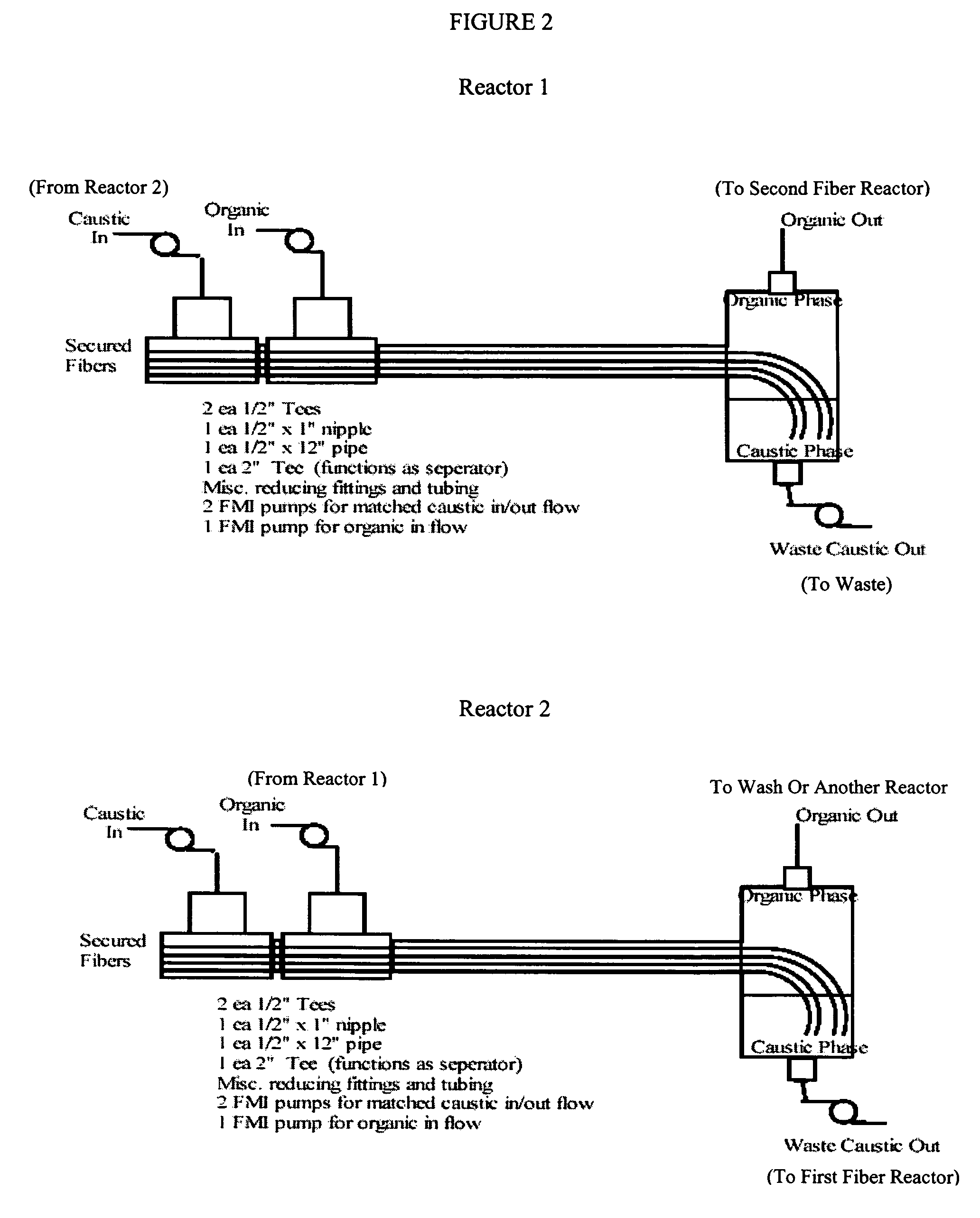
[0036]This example illustrates the use of a conduit reactor comprising a 12″×¼″ stainless steel tube containing approximately 100,000 glass fibers.

[0037]Tests were run with approximately 100,000 glass fibers 17 inches in length in a ¼-inch internal diameter (I.D.) stainless steel tube. The liquid volume of this reactor was approximately 2.9 mL. Two liquids were pumped through this tube, with the constrained phase on the glass fibers being a 23% by weight sodium hydroxide aqueous solution. The continuous phase was a mixture of epichlorohydrin and resin chlorohydrin (made by reacting epichlorohydrin and bisphenol A (BPA) in a 10:1 molar ratio at 70° C. for 24 hours), and included 0.2% tetrabutyl ammonium hydroxide used as a coupling initiator and phase transfer catalyst. The caustic flow rate was 0.5 mL / min. Table 1 shows flow rate, stoichiometry, conversion, and contact time data obtained using the aforementioned reactor for phase transfer catalyzed ring closure of resin chlorohydrin...

example 2

[0039]This example illustrates the use of a conduit reactor comprising a 36″×½″ stainless steel tube with approximately 570,000 glass fibers.

[0040]Tests were run with approximately 570,000 glass fibers 40 inches in length in a ½-inch I.D. The liquid volume of this reactor was approximately 35 mL. Two liquids were pumped through this tube with the constrained phase on the glass fibers being a 23% by weight sodium hydroxide aqueous solution. The continuous phase was a mixture of epichlorohydrin and resin chlorohydrin (made by reacting epichlorohydrin and bisphenol A in a 10:1 molar ratio at 70° C. for 24 hours), with 0.1% tetrabutyl ammonium hydroxide coupling and phase transfer catalyst. The caustic solution was introduced onto the upstream end of the glass fibers at about 12 to about 60 mL per hour. The organic phase was introduced into the conduit and flowed past the fibers at rates varying between about 30 and about 3540 mL per hour. After passing through the fiber reactor, the se...

example 3

[0042]This example illustrates the use of a conduit reactor comprising a 12″×½″ stainless steel tube with approximately 570,000 glass fibers.

[0043]Tests were run with approximately 570,000 glass fibers 16 inches in length in a 12″ outside diameter (O.D.)×½-inch I.D. stainless steel tube. The liquid volume of this reactor was approximately 18 mL. Two liquids were pumped through this tube with the constrained phase on the glass fibers being a 23% by weight sodium hydroxide aqueous solution containing 2% tetrabutyl ammonium hydroxide phase transfer catalyst. The continuous phase was a mixture of benzyl alcohol and benzyl bromide (1:1 molar ratio) in equal weight of toluene. The caustic solution was introduced onto the upstream end of the glass fibers at 60 mL / hr. The organic phase was introduced into the conduit and flowed past the fibers at rate of 270 mL / hr. The reactor was maintained at 75° C. After passing through the fiber reactor, the organic phase separated cleanly from the aque...


PUM

PropertyMeasurementUnit
lengthaaaaaaaaaa
volumeaaaaaaaaaa
flow rateaaaaaaaaaa

Abstract

A fiber reaction process whereby reactive components contained in immiscible streams are brought into contact to effect chemical reactions and separations. The conduit reactor utilized contains wettable fibers onto which one stream is substantially constrained and a second stream is flowed over to continuously create a new interface there between to efficiently bring about contact of the reactive species and thus promote reactions thereof or extractions thereby. Co-solvents and phase transfer catalysts may be employed to facilitate the process.

Description

RELATED APPLICATIONS[0001]This application claims priority benefits to provisional U.S. patent application Ser. No. 60 / 639,444, filed Dec. 22, 2004.GOVERNMENT FUNDING[0002]This invention was made with support from the National Science Foundation Small Business Innovative Research Program, Contract No. DMI-0232067 and Department of Agriculture Small Business Innovative Research Program, Contract No. 2005-33610-15504.FIELD OF THE INVENTION[0003]This invention relates generally to fiber reactors / contactors, and specifically to processes utilizing such devices to effect separation and reaction between two immiscible reaction components using phase transfer catalysts and co-solvents.BACKGROUND OF THE INVENTION[0004]The present invention enables the reaction between constituents of two immiscible fluids in order to produce desirable end products. This is currently achieved by making dispersions of one phase in the other to generate small droplets with a large surface area where mass trans...

Claims


Application Information

Patent Timeline
Patent Type & Authority Patents(United States)
IPC IPC(8): C07C7/148
CPCB01D11/0449B01J14/00B01J19/2415B01J19/2495C07C17/16C11C3/003C07C67/03C07C67/58C11B1/108C11B3/04C07C45/72C07C22/04C07C69/52C07C69/24B01D11/0453Y02P30/20Y02E50/10
Inventor MASSINGILL, JR., JOHN LEE
Owner CHEMTOR LP
Why Eureka
Try Eureka