Equalizer circuit, communication system, and method that is adaptive to varying launch amplitudes for reducing receiver error

a communication system and equalizer technology, applied in the field of data communication, can solve the problems of difficult to maintain accurate matching between the transmission path and the equalizer, the range of adaptive adaptive equalizers of most conventional adaptive equalizers is limited, and the possibility of having to redesign and substitute different equalizers whenever the transmission path is changed, so as to minimize baseline wander and minimize the deleterious jitter and noise in the recovered signal

Inactive Publication Date: 2009-11-17
RPX CORP
View PDF23 Cites 73 Cited by
  • Summary
  • Abstract
  • Description
  • Claims
  • Application Information

AI Technical Summary

Benefits of technology

[0017]In the second embodiment, the feedback circuit which controls the inverse filter includes not only a slicer circuit, but also a voltage detector (i.e., peak detector) coupled to the output of the low-pass filter. The peak detector can measure the peak-to-peak amplitude of the communication signal at the output of the low-pass filter to adjust a DC output from the inverse filter. The adjustment can occur by forwarding the peak detector output to an input of the inverse filter or, alternatively, to an input of the slicer circuit. Regardless of where the peak detector output is connected, the amplitude of the communication signal “launched” from the transmitter is measured via the low-pass filter. The inverse filter or slicer is driven by the peak detector to produce corresponding matched amplitude at the output of the inverse filter or slicer. By matching the launch amplitude within the equalizer, any undershoot or overshoot caused by respective under-compensation or over-compensation can be eliminated across a relatively wide launch amplitude range.
[0018]The first embodiment describing an improved inverse filter can be used with or without the second embodiment of an improved feedback mechanism for adjusting gain and / or frequency response of that inverse filter. Preferably, however, both embodiments can be implemented into a single communication system to achieve a more optimal result. That result being one which performs closer matching of the inverse filter transfer function to that of the transmission path by minimizing baseline wander with variations in communication signal pattern density, and thus minimizing the resulting deleterious jitter and noise in the recovered signal.

Problems solved by technology

One problem with the first approach is the implausibility in having to redesign and substitute different equalizers whenever the transmission path changes.
Moreover, it is often difficult to maintain accurate matching between the transmission path and the equalizer if either one of those components should change with changes in fabrication processes, or changes in temperature or voltage during operation.
If the second approach is to be used, most conventional adaptive equalizers have a limited range to which they can adapt.
For example, an adaptive equalizer cannot provide a matching inverse frequency response if the transmission path extends beyond a maximum range.
If a communication signal amplitude extends outside that range, then exact equalization may not be possible.

Method used


Image

  • Equalizer circuit, communication system, and method that is adaptive to varying launch amplitudes for reducing receiver error
  • Equalizer circuit, communication system, and method that is adaptive to varying launch amplitudes for reducing receiver error
  • Equalizer circuit, communication system, and method that is adaptive to varying launch amplitudes for reducing receiver error

Examples


Embodiment Construction

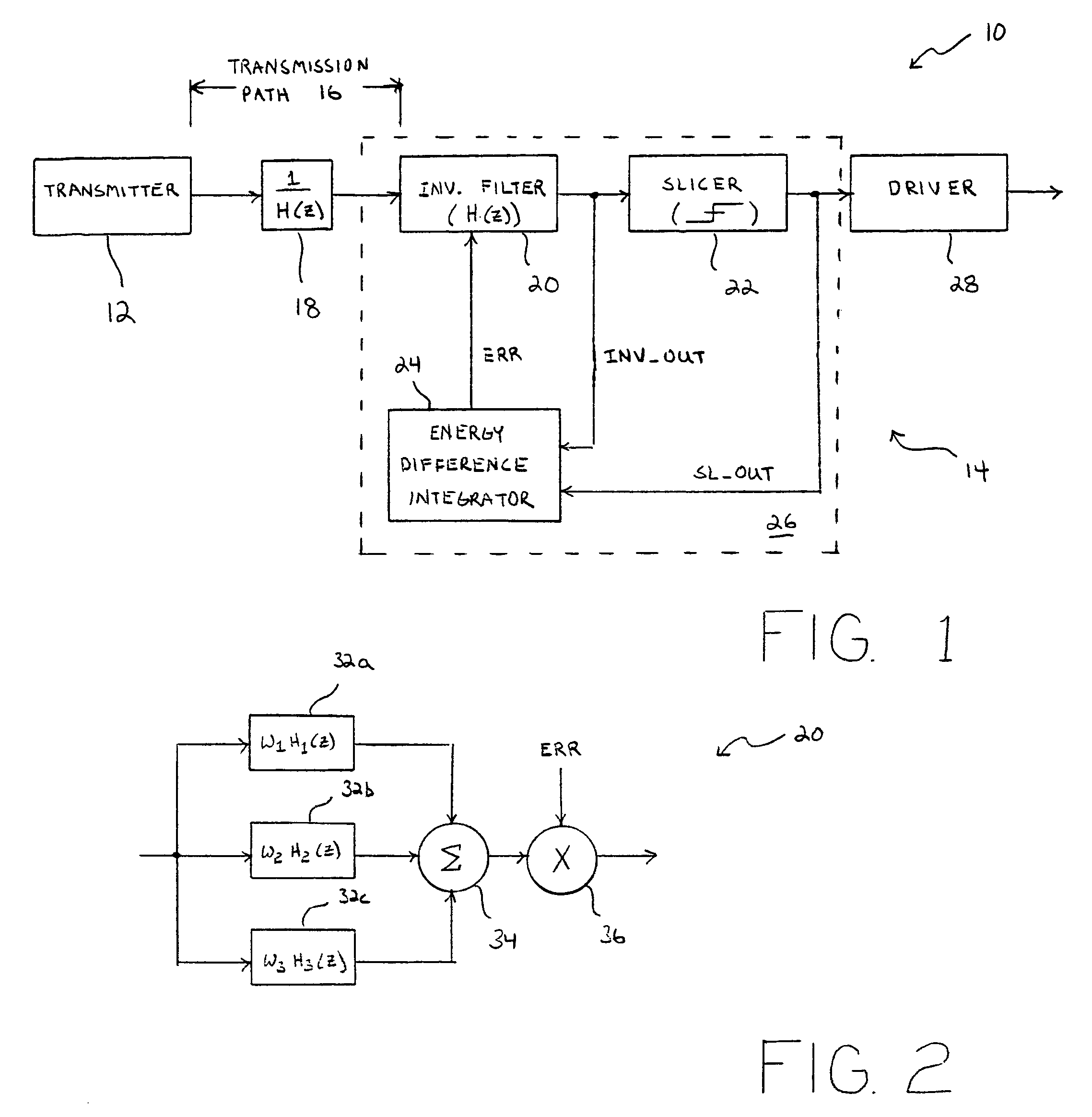
[0036]Turning now to the drawings, FIG. 1 illustrates a communication system 10 that comprises a transmitter 12, a receiver 14, and a transmission path 16. Transmitter 12 can be any electronic subsystem that produces a modulated and / or coded communication signal across path 16. Path 16 is connected between transmitter 12 and receiver 14, and includes either a wireless or wired transmission medium. As shown in block 18, transmission path 16 exhibits a low-pass characteristic of transmitting low frequency components more readily than high frequency components of the communication signal. High-pass characteristic is denoted as H(z) and, thus, low-pass characteristic is represented in block 18 as 1 / H(z).

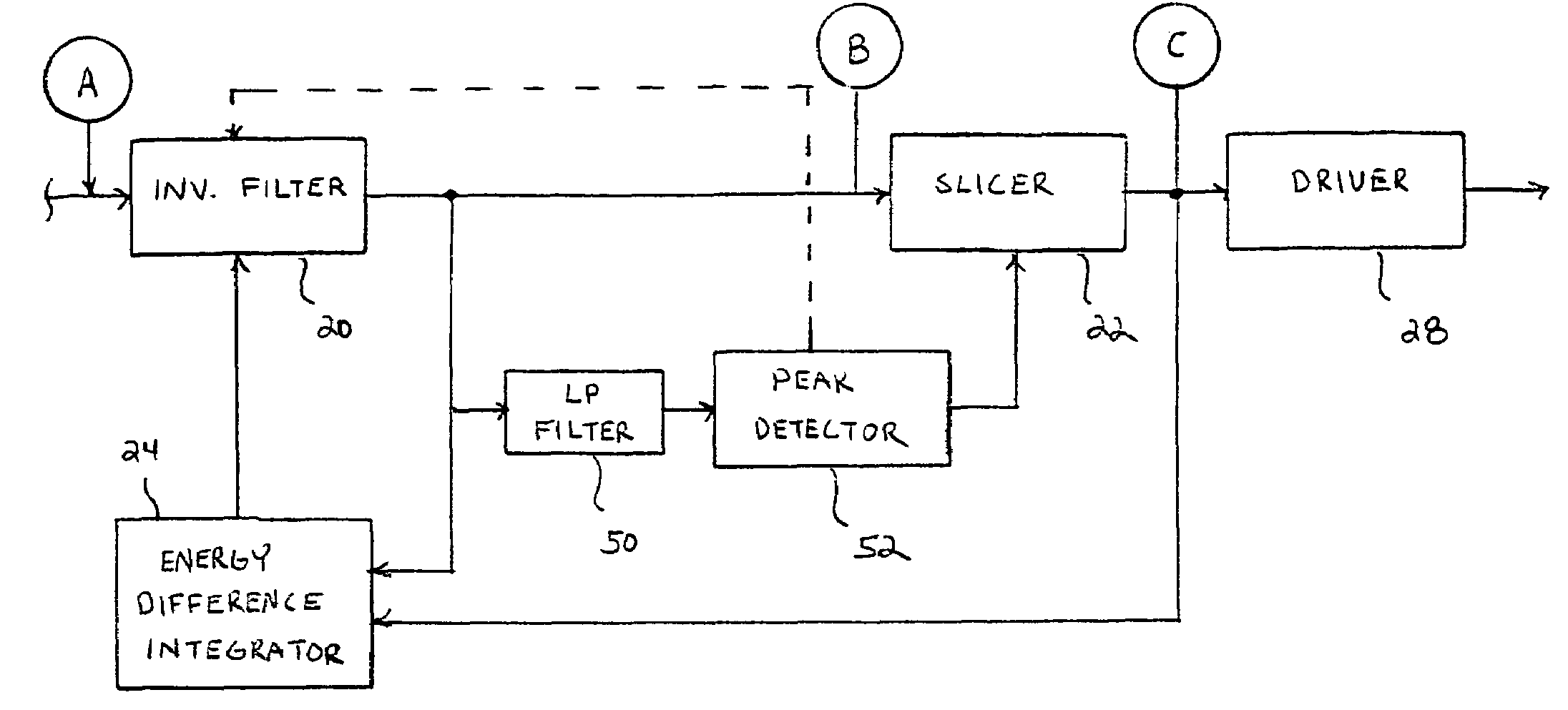
[0037]To compensate for the low-pass characteristic shown in block 18, an inverse filter having a high-pass characteristic H(z) is shown in block 20. Coupled to the output of inverse filter 20 is a comparator, or slicer 22. Slicer 22 compares the output from filter 20 to a threshold volt...


PUM


Abstract

A transmission line equalizer, communication system, and method are provided for adaptively compensating for changes in transmission path length and transmission path medium. Within the equalizer is a filter that exhibits a high pass characteristic and, more specifically, has an inverse frequency response to that of the transmission path. The inverse filter can include a pair of amplifier stages coupled in parallel, with a mixer chosen to adaptively select portions of one stage over than of the other. The dual stage inverse filter can, therefore, adapt to greater transmission path lengths and/or attenuation. A feedback architecture is used to set the inverse filter response by measuring the amplitude of a communication signal output from the inverse filter during periods of low frequency. A peak detector will capture a peak-to-peak voltage value during those periods, and adjust the output of the slicer to match a launch amplitude of the communication signal. The peak detector within the feedback architecture helps ensure the predicted amplitude matches the launch amplitude to minimize over-compensation or under-compensation even though a different integrator might register no difference in integrated voltage or energy at the output of the inverse filter compared to the output of the slicer.

Description

PRIORITY APPLICATION[0001]This application claims priority to Provisional Application No. 60 / 505,706 entitled “Improved Equalizer Architecture,” filed Sep. 24, 2003.BACKGROUND OF THE INVENTION[0002]1. Field of the Invention[0003]The present invention relates to the field of data communication and, more particularly, to an equalizer circuit, communication system and method for receiving a communication signal sent across a transmission channel and for accurately recovering the communication signal having a wide variance of communication signal launch amplitude, wide performance fluctuations in the transmitter or equalizer, or the length / attenuation of the transmission channel.[0004]2. Description of the Related Art[0005]The following descriptions and examples are not admitted to be prior art or conventional by virtue of their inclusion within this section.[0006]A data communication system typically involves a transmitter and a receiver connected by a transmission path. The transmitte...

Claims


Application Information

Patent Timeline
Patent Type & Authority Patents(United States)
IPC IPC(8): H04B1/66
CPCH04B3/143
Inventor JENKINS, JULIAN
Owner RPX CORP
Why Eureka
Try Eureka