
Formable, porous, chemiluminescent reactant composition and device therefor

a technology of chemiluminescent and reactant composition, which is applied in the field of chemiluminescent compositions, can solve the problems of limited to a two-dimensional surface, limited to producing a single color of light per device, and difficult to rapidly and completely activate the oxalate in the tubing

Inactive Publication Date: 2009-11-24
CYALUME TECH
View PDF21 Cites 10 Cited by
  • Summary
  • Abstract
  • Description
  • Claims
  • Application Information

AI Technical Summary

Benefits of technology

[0021]The instant invention teaches a means to produce three-dimensional objects which are self-illuminated. The objects may be as simple or as complex as desired. The objects are produced by a method employing a formable, chemiluminescent reactant composition. This composition is of such a nature that it may be readily placed in variously shaped containers and then cured in said containers whereupon the composition becomes solid and is of a shape that precisely matches the container in which it was formed. Once formed, the composition is semi-rigid and may be removed from the container if desired. Additionally, the instant invention provides for a chemiluminescent reactant composition which is exceptionally porous and is not limited to relatively flat strips of material, as is the case in prior art. Also, objects produced by means of the instant invention may be hollow so that a minimal amount of material may be used to produce glowing, three-dimensional objects. Further, these objects may be multi-colored, that is, a single object can be created which is capable of simultaneously generating a plurality of spatially separated colors or wavelengths of chemiluminescent light.
[0022]A fundamental objective of the instant invention is that a significant portion of the interstitial spaces in the solid product necessary for quick and reliable activation by a liquid activator is created prior to curing. As such, the system does not rely primarily on porosity created during the curing process in which the air must enter the matrix from outside. Since the final porosity of the product of the instant invention is primarily a function of the degree of densification prior to curing, the final porosity of the product may be precisely and advantageously controlled.
[0026]It is a further objective of the instant invention to provide for a three-dimensional chemiluminescent object in which the porosity can be readily and precisely controlled.
[0027]It is a still further objective of the invention to provide for a three-dimensional chemiluminescent object which may be produced by forming in a mold which may not permit significant expansion of the chemiluminescent reactant composition during the curing process.
[0031]It is yet another objective of the instant invention to provide for a formulation for a chemiluminescent reactant composition which is formable and as such, may be readily formed into a desired shape either with or without the use of a mold or form.

Problems solved by technology

Although the shape may be as simple or as complex as desired, it is essentially limited to a two-dimensional surface and is additionally limited to producing a single color of light per device.
Since the solid polymer is relatively non-porous, it is difficult to rapidly and completely activate the oxalate in the tubing because the relatively slow process of diffusion must also be relied upon to permit the activator solution to reach the chemiluminescent reagent diffused into the polymer before light can be generated.
While this embodiment is operative, the polyvinyl chloride sheet described exhibits weaknesses in uniformity, strength, flexibility, and most importantly, porosity.
Although an improvement in the art, the products produced still suffer from a variety of shortcomings, particularly if solid, chemiluminescent objects are to be produced which are other than relatively flat, thin objects.
As such, the slurry and hence, the resulting pad shape, is limited to the shape of the mold, into which the slurry is poured and pools.
Consequently, it is incapable of rapidly absorbing liquid activator solution and as such, minimally contributes to light output of the device.
The thickness of this skin varies with the time and temperature of the baking process, but in any event, this skin represents wasted material from which little usable light may be produced.
It has been determined that this skin is created by an inability of the slurry to draw in air (or other gasses) during the baking process.
Due to a lack of air available to this jelling slurry, this “bottom up” curing process results in a pad which is tough, dense, and virtually non-porous in the region of the pad proximal to the mold bottom and to a lesser extent, the mold edges.
Nonetheless, the undesirable production of a tough and impermeable skin layer remains unaddressed.
As a result, significant problems develop when attempting to cure a relatively large mass of this slurry.
For example, if a liquid slurry mixture, as taught in the '218 patent, is poured into a test tube and baked for the appropriate time to cure, a dense, tough mass will be produced exhibiting very poor porosity and hence, poor absorbency throughout most of the mass.
This is due in part to the “bottom up” curing process described above wherein insufficient air is drawn into the slurry during the curing process due to the existence of an air tight liquid layer above the slurry being cured near the mold bottom.
As such, the cured mass will exhibit low porosity and yield poor light output which is a limitation of the art.
Although this device provides a controllable duration or stability of light, there is no suggestion of a composition to control the generation of gas produced or a composition which may be independent of a container, i.e. not formable or porous.
In addition, the prior art fails to contemplate a product which may be independent of a container, minimizes dark areas due to gas generation, and which is capable of generating a plurality of spatially separated or wavelengths of chemiluminescent light simultaneously.

Method used


Image

  • Formable, porous, chemiluminescent reactant composition and device therefor
  • Formable, porous, chemiluminescent reactant composition and device therefor
  • Formable, porous, chemiluminescent reactant composition and device therefor

Examples


examples 1-6

[0056]Six tests were conducted to determine the effects of varying cure times and temperatures as well as slurry thickness on porosity. In each test, approximately 7 grams of liquid slurry was placed in a small aluminum weighing pan which was then positioned on a spacer such that the pan bottom was slightly inclined to create a slurry having a depth ranging from 0.015″ to 0.180″. During each test, the pan was placed on a wire rack in a circulating air oven. After curing for the specified time, each sample item was removed from the pan, sectioned, and examined for proper curing and porosity. A properly cured sample is defined as one in which all of the oxalate solution had been absorbed into the PVC matrix, and which does not exhibit signs of over-curing. In a properly cured matrix, the lower molecular weight PVC particles fuse together. However, the higher molecular weight PVC particles, while absorbing the liquid oxalate solution, do not significantly fuse together. If the curing t...

example 7

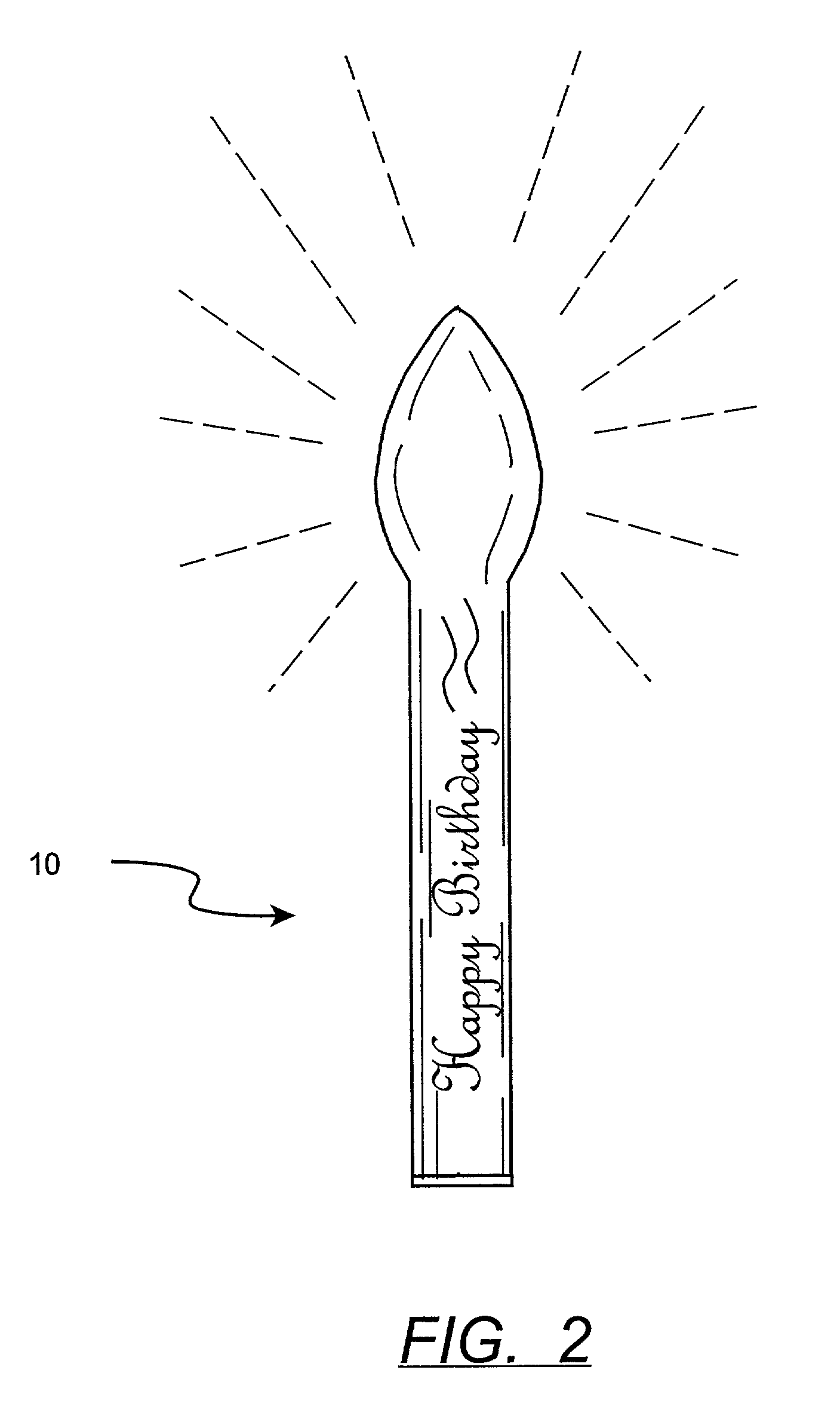
[0061]A chemiluminescent candle was produced using the same liquid slurry formation as that used in tests 1-6 above. To make this candle, approximately 3.2 grams of liquid slurry was injected into a polyethylene candle envelope using a syringe. A glass ampoule containing chemiluminescent activator was inserted into this slurry such that the lower end of the ampoule contacted the inside bottom of the candle envelope. The assembly was placed in a circulating air oven set for 82° C. and allowed to cure for 12 minutes. After removal, the assembly was allowed to cool to room temperature whereupon the candle envelope and cured slurry were sectioned for observation. The PVC matrix (cured slurry) appeared to be fully cured, but was dark and dense. The PVC matrix portions were removed from the envelope and placed in an aluminum weighing pan. Chemiluminescent activator reagent was added to these portions whereupon the cured slurry glowed dimly. It was observed that the activator was reacting ...

example 8

[0062]With these results in mind, an aliquot of slurry was supported upon an air permeable substrate, e.g. a 10 cm by 10 cm section of 2 mm thick non-woven polyester felt and placed in a circulating air oven, maintained at 82° C., for 8 minutes. The expectation was that the felt would provide uniform access of air to the slurry and that heat would cure the slurry from the outside in such a manner that no dark, non-porous regions would be formed as had been the case in slurry previously cured in the impermeable aluminum pans. As each successive layer of the slurry cured from the outside in, it would become porous, thereby allowing air to reach subsequent layers. This sample was removed from the oven and allowed to cool. Upon inspection, it was noted that the pad had no dark or dense areas and was extremely porous. The sample was activated with chemiluminescent activator reagent whereupon the sample glowed brightly and evenly throughout its entirety.

[0063]A model which explains the fo...


PUM

PropertyMeasurementUnit
Particle sizeaaaaaaaaaa
Compositionaaaaaaaaaa
Coloraaaaaaaaaa

Abstract

A formable, porous chemiluminescent reactant composition, device therefore, and a process for production thereof is disclosed. The fluidizable solid admixture of the instant invention may be cured to a more or less rigid form with or without the use of a mold. The cured solid is useful as a chemiluminescent reactant component and is useful in a variety of environments.

Description

FIELD OF THE INVENTION[0001]This invention is directed toward the field of chemiluminescent compositions and more particularly, to devices which produce light from an immobilized chemiluminescent material.BACKGROUND OF THE INVENTION[0002]The term “chemiluminescent reactant”, “chemiluminescently reactive” or “chemiluminescent reactant composition” is interpreted to mean a mixture or component thereof which will result in chemiluminescent light production when reacted with other necessary reactants in the processes as disclosed herein.[0003]The term “fluorescent compound” is interpreted to mean a compound which fluoresces in a chemiluminescent reaction, or a compound which fluoresces in a chemiluminescent reaction.[0004]The term “chemiluminescent composition” is interpreted to mean a mixture which will result in chemiluminescence.[0005]The term “deagglomerate” is interpreted to mean to break up or loosen a compacted portion of a cluster or a mass.[0006]The term “fluidizable solid admi...

Claims


Application Information

Patent Timeline
IPC IPC(8): C09K3/00F21K2/06C08K11/00C08K5/10C08L101/00C09K11/07
CPCC09K11/07Y10T428/1379
Inventor PALMER, WILLIAM R.PALMER, STEPHEN L.CRANOR, EARL
Owner CYALUME TECH
Learn More