

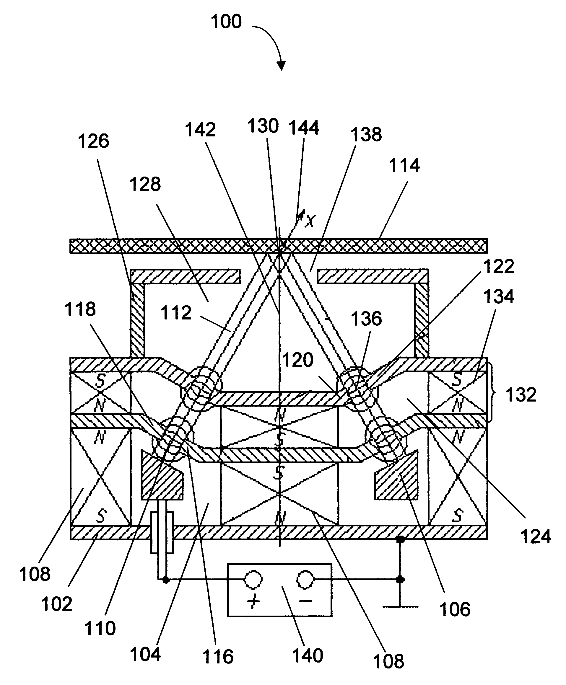
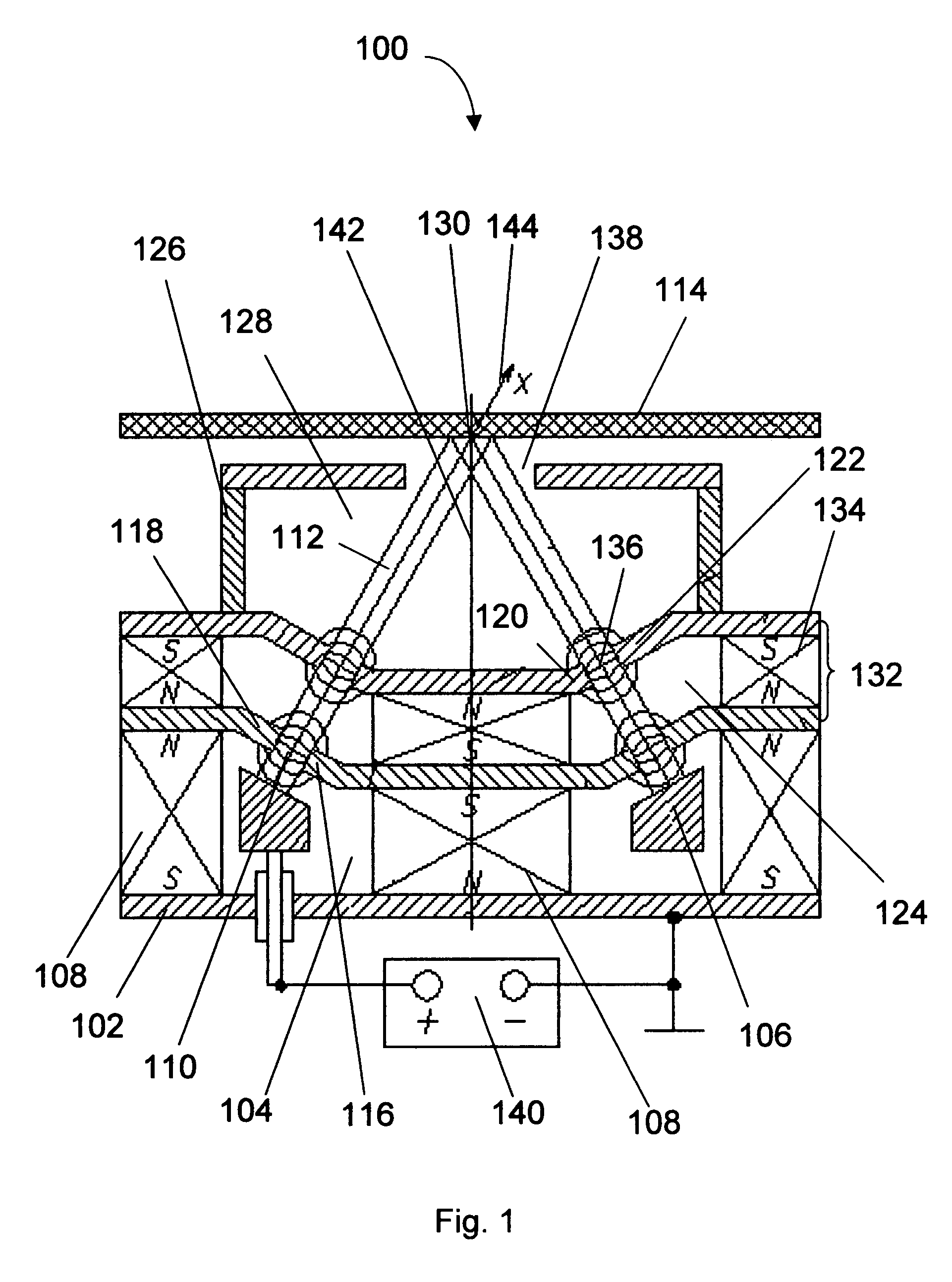
Focused anode layer ion source with converging and charge compensated beam (falcon)
a plasma accelerator and ion beam technology, applied in the field of plasma technology, can solve the problems of reducing the efficiency of ion treatment, preventing their wide acceptance for use in thin film technology, sputtering cathode material, etc., and achieves the effect of increasing plasma intensity, increasing plasma intensity, and increasing plasma intensity
- Summary
- Abstract
- Description
- Claims
- Application Information
AI Technical Summary
Benefits of technology
Problems solved by technology
Method used
Image

Examples
example 1
[0050]An argon ion beam for the ion milling of an aluminum nitride (AlN) film was generated. The ion source had a round ion emitting aperture with an outside diameter of 30 mm. The operational gas was Ar at a pressure of 4.5×10⁻⁵ Torr. The anode voltage was 3 KV, the discharge current was 27 mA. An ion beam was directed at the AlN film deposited on a Si wafer. The treated part was fixed relative to the ion source (static mode). The average ion milling rate of the AlN film was 3500 A / min. The outside diameter of the spot etched in the AlN film was 5 mm. Following 30 minutes of operation in static mode the AlN film was found to contain no contamination. The potential of the surface of the AlN film did not exceed 100 V, which corresponds to a less than 10% loss in beam energy and essentially no loss of the ions in the ion beam.
PUM
 Abstract
Description
Claims
Application Information