Thermally stable ultra-hard polycrystalline materials and compacts

a polycrystalline material, ultra-hard technology, applied in the direction of solventing apparatus, other manufacturing equipment/tools, manufacturing tools, etc., can solve the problems of thermal degradation, cracks and chips in the pcd structure, diamond-to-diamond bonding rupture, etc., to improve the thermal stability, wear resistance and hardness, and facilitate the attachment of the compact

Inactive Publication Date: 2009-12-08
SMITH INT INC
View PDF147 Cites 67 Cited by
  • Summary
  • Abstract
  • Description
  • Claims
  • Application Information

AI Technical Summary

Benefits of technology

[0013]Thermally stable ultra-hard polycrystalline materials and compacts of this invention generally comprise an ultra-hard polycrystalline body including one or more thermally stable ultra-hard polycrystalline regions disposed therein. The ultra-hard polycrystalline body may additionally comprise a substrate attached or integrally joined to the body, thereby providing a thermally stable diamond bonded compact.
[0016]Thermally stable ultra-hard polycrystalline materials and compacts formed therefrom according to principles of this invention have improved properties of thermal stability, wear resistance and hardness when compared to conventional ultra-hard materials, such as conventional PCD materials, and include a substrate to facilitate attachment of the compact to an application device by conventional method such as welding or brazing and the like.

Problems solved by technology

A problem known to exist with such conventional PCD materials is thermal degradation due to differential thermal expansion characteristics between the interstitial solvent catalyst material and the intercrystalline bonded diamond.
Such differential thermal expansion is known to occur at temperatures of about 400° C., causing ruptures to occur in the diamond-to-diamond bonding, and resulting in the formation of cracks and chips in the PCD structure.
Another problem known to exist with conventional PCD materials is also related to the presence of the solvent catalyst material in the interstitial regions and the adherence of the solvent catalyst to the diamond crystals to cause another form of thermal degradation.
Specifically, the solvent catalyst material is known to cause an undesired catalyzed phase transformation in diamond (converting it to carbon monoxide, carbon dioxide, or graphite) with increasing temperature, thereby limiting practical use of the PCD material to about 750° C.
However, the resulting thermally stable PCD body typically does not include a metallic substrate attached thereto by solvent catalyst infiltration from such substrate due to the solvent catalyst removal process.
This difference in thermal expansion between the thermally stable PCD body and the substrate, and the poor wetability of the thermally stable PCD body diamond surface makes it very difficult to bond the thermally stable PCD body to conventionally used substrates, thereby requiring that the PCD body itself be attached or mounted directly to a device for use.
However, since such conventional thermally stable PCD body is devoid of a metallic substrate, it cannot (e.g., when configured for use as a drill bit cutter) be attached to a drill bit by conventional brazing process.
The use of such thermally stable PCD body in this particular application necessitates that the PCD body itself be mounted to the drill bit by mechanical or interference fit during manufacturing of the drill bit, which is labor intensive, time consuming, and which does not provide a most secure method of attachment.
Additionally, because such conventional thermally stable PCD body no longer includes the solvent catalyst material, it is known to be relatively brittle and have poor impact strength, thereby limiting its use to less extreme or severe applications and making such thermally stable PCD bodies generally unsuited for use in aggressive applications such as subterranean drilling and the like.

Method used


Image

  • Thermally stable ultra-hard polycrystalline materials and compacts
  • Thermally stable ultra-hard polycrystalline materials and compacts
  • Thermally stable ultra-hard polycrystalline materials and compacts

Examples


embodiment 26

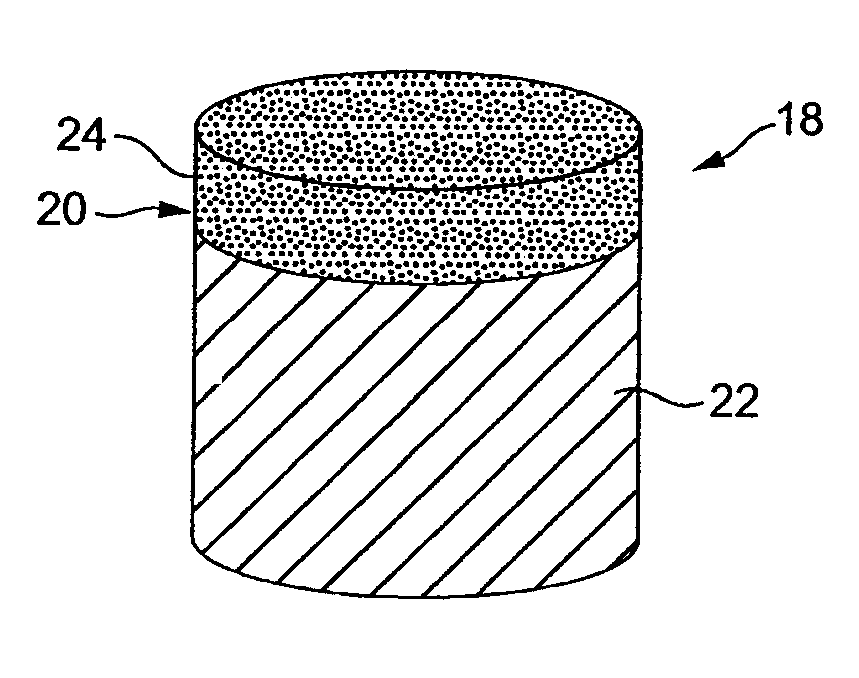
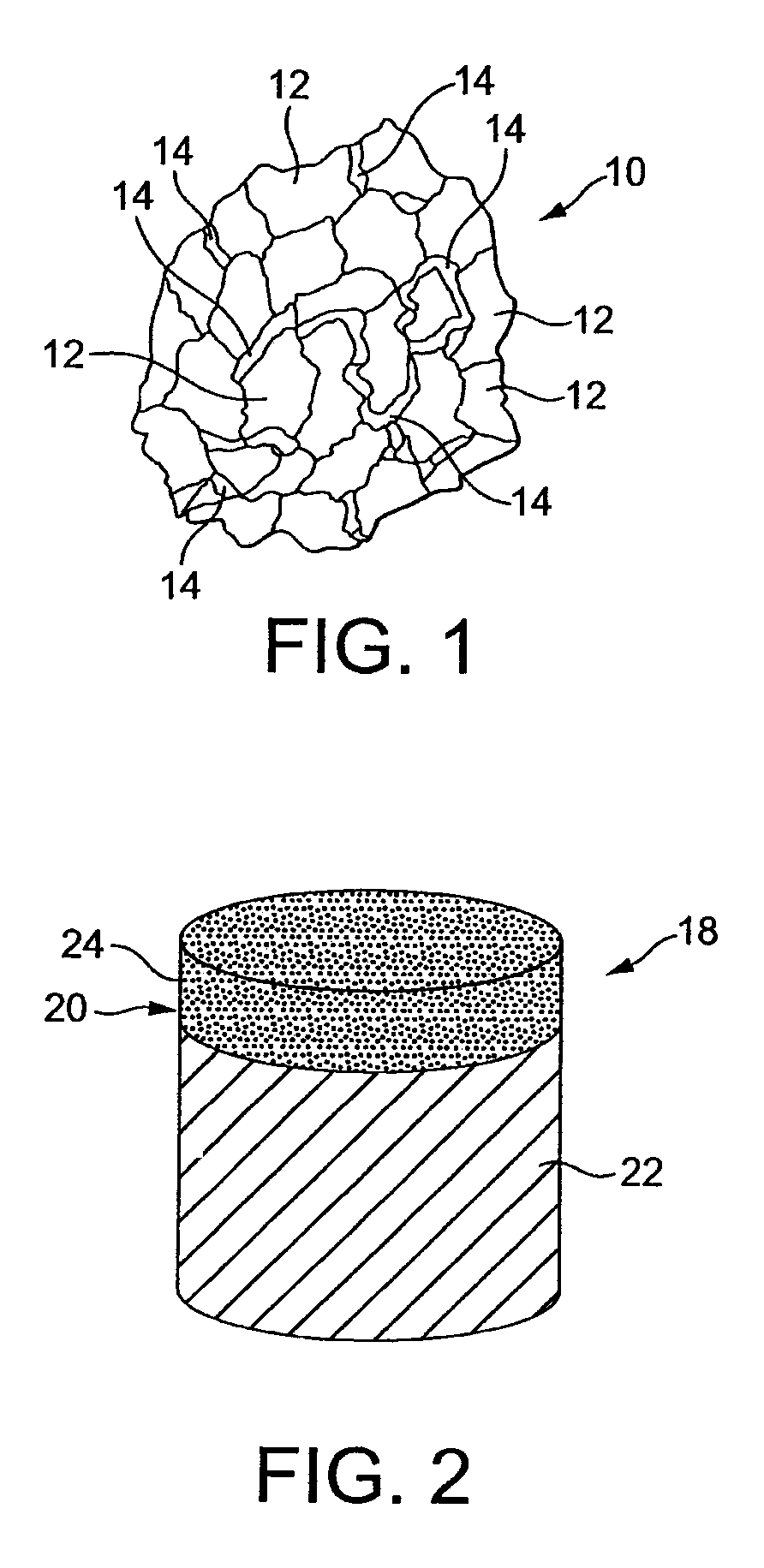
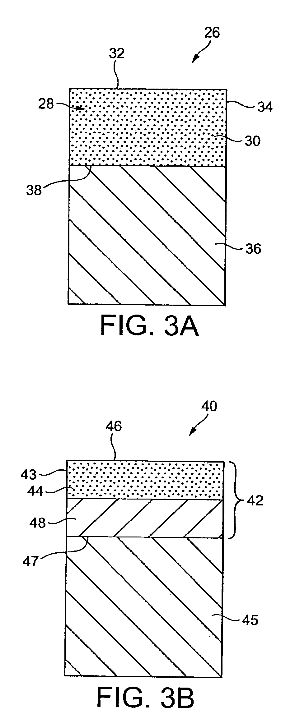
[0040]FIGS. 3A to 3D illustrate different embodiments of thermally stable ultra-hard polycrystalline compacts constructed in accordance with the principles of this invention. FIG. 3A illustrates a compact embodiment 26 comprising a polycrystalline body 28 that is formed entirely from the thermally stable ultra-hard polycrystalline material 30 according to the HPHT process disclosed above. The body 28 includes a working surface that can extend along the body top surface 32 and / or side surface 34, and is attached to a substrate 36 along an interface surface 38. The interface surface can be planar or nonplanar.

[0041]The body 30 can be attached to the substrate 26 by brazing or welding technique, e.g., by vacuum brazing. Alternatively, the body can be attached to the substrate by combining the body and substrate together, and then subjecting the combined body and substrate to a HPHT process. If needed, an intermediate material can be interposed between the body and the substrate to faci...

embodiment 40

[0042]FIG. 3B illustrates a compact embodiment 40 comprising an ultra-hard polycrystalline body 42 that is only partially formed the thermally stable ultra-hard polycrystalline material 44. The body 42 is attached to a substrate 45, and the body / substrate interface 47 can be planar or nonplanar. In this particular embodiment, the thermally stable ultra-hard polycrystalline material 44 occupies an upper region of the body 42 that extends a depth from a top surface 46 of the body. Alternatively, the thermally stable ultra-hard polycrystalline material 44 can be positioned to occupy a different surface of the body that may or may not be a working surface, e.g., it can be positioned along a sidewall surface 43 of the body. The exact thickness of the region occupied by the thermally stable ultra-hard polycrystalline material 44 in this embodiment is understood to vary depending on the particular end use application, but can extend from about 5 to 3,000 microns.

[0043]The remaining portion...


PUM

PropertyMeasurementUnit
temperaturesaaaaaaaaaa
temperatureaaaaaaaaaa
sizeaaaaaaaaaa

Abstract

Thermally stable ultra-hard polycrystalline materials and compacts comprise an ultra-hard polycrystalline body that wholly or partially comprises one or more thermally stable ultra-hard polycrystalline region. A substrate can be attached to the body. The thermally stable ultra-hard polycrystalline region can be positioned along all or a portion of an outside surface of the body, or can be positioned beneath a body surface. The thermally stable ultra-hard polycrystalline region can be provided in the form of a single element or in the form of a number of elements. The thermally stable ultra-hard polycrystalline region can be formed from precursor material, such as diamond and / or cubic boron nitride, with an alkali metal catalyst material. The mixture can be sintered by high pressure / high temperature process.

Description

RELATION TO COPENDING PATENT APPLICATION[0001]This invention claims priority from U.S. Provisional Patent Application Ser. No. 60 / 771,722 filed on Feb. 9, 2006, and which is incorporated herein in its entirety by reference.FIELD OF THE INVENTION[0002]This invention generally relates to ultra-hard materials and, more specifically, to ultra-hard polycrystalline materials and compacts formed therefrom that are specially engineered having improved properties of thermal stability, wear resistance and hardness when compared to conventional ultra-hard polycrystalline materials such as conventional polycrystalline diamond.BACKGROUND OF THE INVENTION[0003]Polycrystalline diamond (PCD) materials and PCD elements formed therefrom are well known in the art. Conventional PCD is formed by combining diamond grains with a suitable solvent catalyst material to form a mixture. The mixture is subjected to processing conditions of extremely high pressure / high temperature (HP / HT), where the solvent cata...

Claims


Application Information

Patent Timeline
Patent Type & Authority Patents(United States)
IPC IPC(8): E21B10/36
CPCC22C26/00E21B10/5676E21B10/573B22F7/08B22F7/062B22F3/14B23K1/00B22F1/0003B22F3/24B22F2005/002B22F2998/00B22F2998/10B22F1/12E21B10/46E21B10/50E21B10/52E21B10/56E21B10/5735
Inventor MIDDLEMISS, STEWART N.
Owner SMITH INT INC
Why Eureka
Try Eureka