
Exhaust gas purifying catalyst and production process thereof

a technology of exhaust gas and purifying catalyst, which is applied in the direction of physical/chemical process catalyst, metal/metal-oxide/metal-hydroxide catalyst, separation process, etc., can solve the problems of failure to meet the heat resistance required in such usage, and achieve the effect of improving the heat resistance of the surface layer and the oxygen conductivity of the surface layer

Inactive Publication Date: 2009-12-15
TOYOTA JIDOSHA KK
View PDF14 Cites 3 Cited by
  • Summary
  • Abstract
  • Description
  • Claims
  • Application Information

AI Technical Summary

Benefits of technology

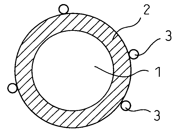
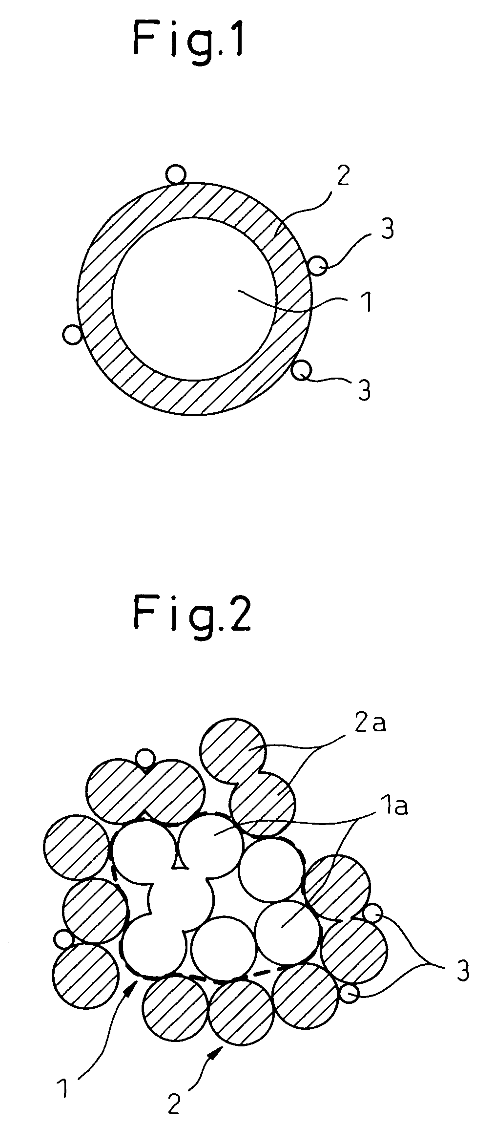
[0011]According to the exhaust gas purifying catalyst of the present invention, a metal oxide particle comprising a core part relatively rich in ceria and a surface layer relatively rich in zirconia is used, so that OSC provided by ceria in the core part and high heat resistance attributable to zirconia in the surface layer can be achieved. Furthermore, excellent catalyst activity can be achieved owing to the combination of zirconia in the surface layer and rhodium supported thereon.
[0015]According to these embodiments, OSC provided by ceria in the core part and high heat resistance attributable to zirconia in the surface layer can be satisfactorily achieved.
[0018]According to this embodiment, the heat resistance and the OSC of the core part relatively rich in ceria can be enhanced.
[0020]According to this embodiment, the oxygen conductivity of the surface layer is improved and therefore, the OSC provided by ceria in the core part can be satisfactorily utilized. Furthermore, according to this embodiment, heat resistance of the surface layer is improved.

Problems solved by technology

In this way, ceria has preferred properties for use in an exhaust gas purifying catalyst, but sometimes fails in satisfying heat resistance required in such usage.

Method used


Image

  • Exhaust gas purifying catalyst and production process thereof
  • Exhaust gas purifying catalyst and production process thereof
  • Exhaust gas purifying catalyst and production process thereof

Examples


example 1

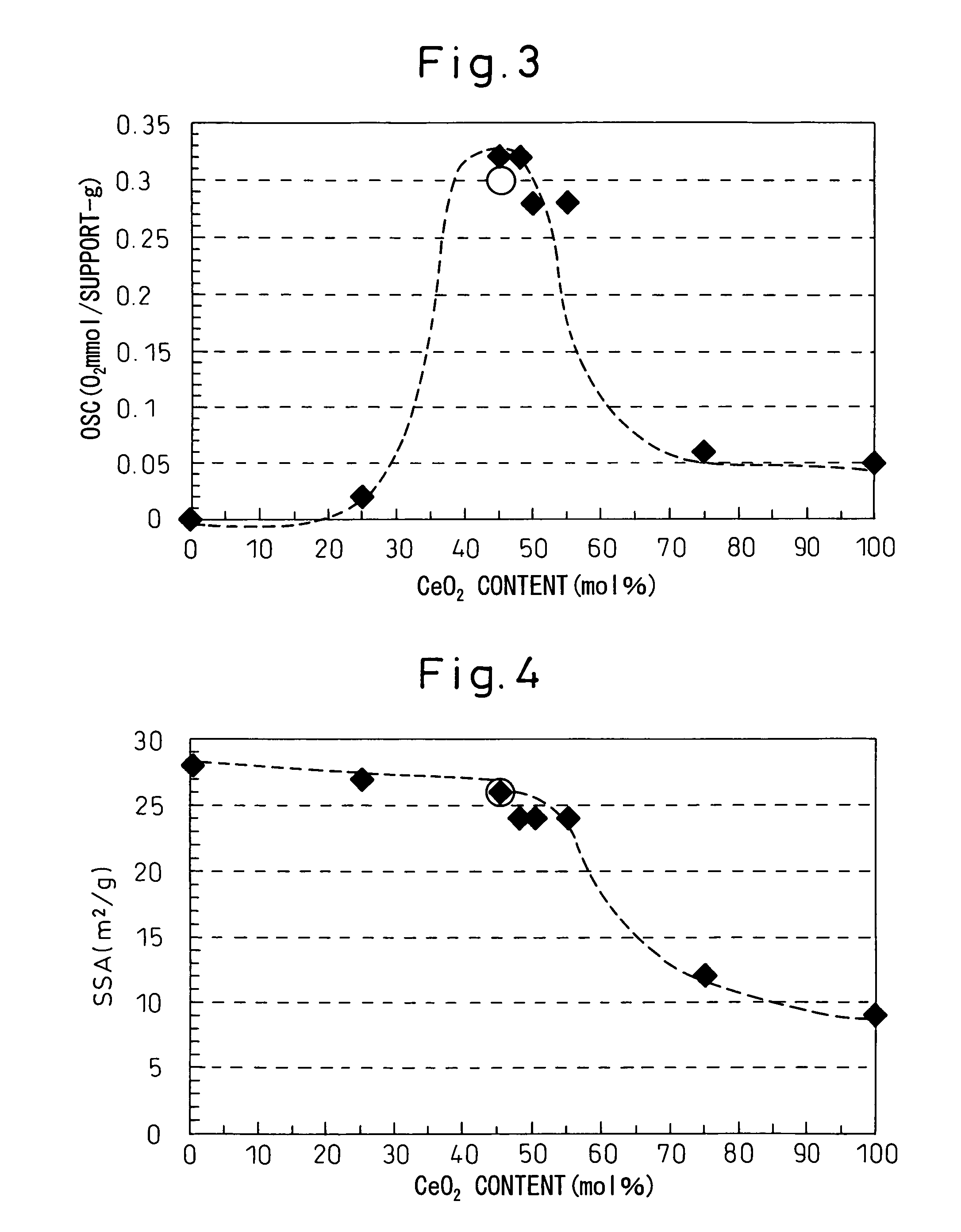
[0062]In this Example, a metal oxide particle comprising a core part relatively rich in ceria and a surface layer relatively rich in zirconia (CeO2:ZrO2:Y2O3=45:52:3 (by mol)) is obtained, and rhodium is supported thereon.

[0063]An alkali-stabilized ceria sol (isoelectric point: pH 3.5), an acid-stabilized zirconia sol (isoelectric point: pH 8.5) and an yttria sol were mixed to give the above-described molar ratio, thereby rendering the sol mixture acidic and aggregating ceria. Thereafter, an aqueous 5M ammonia (NH3) solution was added dropwise with stirring to adjust the pH to 11, thereby aggregating zirconia. The resulting solution was dried at 120° C. for 24 hours, and the dried product was fired at 700° C. for 5 hours to obtain metal oxide particles.

[0064]The thus-obtained metal oxide particles were dispersed in distilled water which was in an amount of 6-fold weight, a rhodium nitrate solution was added thereto so that rhodium is in an amount of 0.5 wt % based on the metal oxide...

example 2

[0065]In this Example, a catalyst was obtained in the same manner as in Example 1 except that the molar ratio of components in the metal oxide particle was changed to CeO2:ZrO2:Y2O3=48:49:3.

example 3

[0066]In this Example, a catalyst was obtained in the same manner as in Example 1 except that the molar ratio of components in the metal oxide particle was changed to CeO2:ZrO2:Y2O3=25:72:3.


PUM

PropertyMeasurementUnit
particle diameteraaaaaaaaaa

Abstract

The present invention provides an exhaust gas purifying catalyst and a production process thereof. An exhaust gas purifying catalyst of the present invention comprises a metal oxide particle (1, 2) and rhodium (3) supported thereon, the metal oxide particle (1, 2) comprising a core part (1) relatively rich in ceria and a surface layer (2) relatively rich in zirconia.

Description

TECHNICAL FIELD[0001]The present invention relates to an exhaust gas purifying catalyst and a production process thereof.RELATED ART[0002]The exhaust gas from internal combustion engines such as automobile engines contains nitrogen oxide (NOx), carbon monoxide (CO), hydrocarbon (HC) and the like. These substances can be purified by an exhaust gas purifying catalyst capable of oxidizing CO and HC and at the same time, reducing NOx. As for representative exhaust gas purifying catalysts, three-way catalysts where a noble metal such as platinum (Pt), rhodium (Rh) and palladium (Pd) is supported on a porous metal oxide support such as γ-alumina are known.[0003]The metal oxide support may be formed of various materials but, in order to obtain a high surface area, alumina (Al2O3) has been heretofore generally used. However, in recent years, for accelerating purification of the exhaust gas by using the chemical properties of the support, it has been proposed to use various other materials s...

Claims


Application Information

Patent Timeline
Patent Type & Authority Patents(United States)
IPC IPC(8): B01J23/10B01D53/94B01J21/06F01N3/10B01J23/63B01J35/00B01J37/03
CPCB01D53/945B01J23/10B01J23/63B01J37/03Y02T10/22B01D2255/1025B01D2255/206B01D2255/20715B01D2255/407B01D2255/902B01D2255/908B01J21/066B01J35/0006B01J35/0013B01J35/023B01D2255/102Y02T10/12
Inventor MIURA, MASAHIDE
Owner TOYOTA JIDOSHA KK
Learn More