Module type multiphase inverter
a multi-phase inverter and module technology, applied in the direction of printed circuit board receptacles, electrical apparatus construction details, support structure mounting, etc., can solve the problems of undesired complexity of packaging chips into modules, surge noise, undesired complexity of connection of wires with terminals, etc., to simplify the wiring of power supplies, simplify the manufacture of inverters, and efficiently radiate heat
- Summary
- Abstract
- Description
- Claims
- Application Information
AI Technical Summary
Benefits of technology
Problems solved by technology
Method used
Image
Examples
embodiment 1
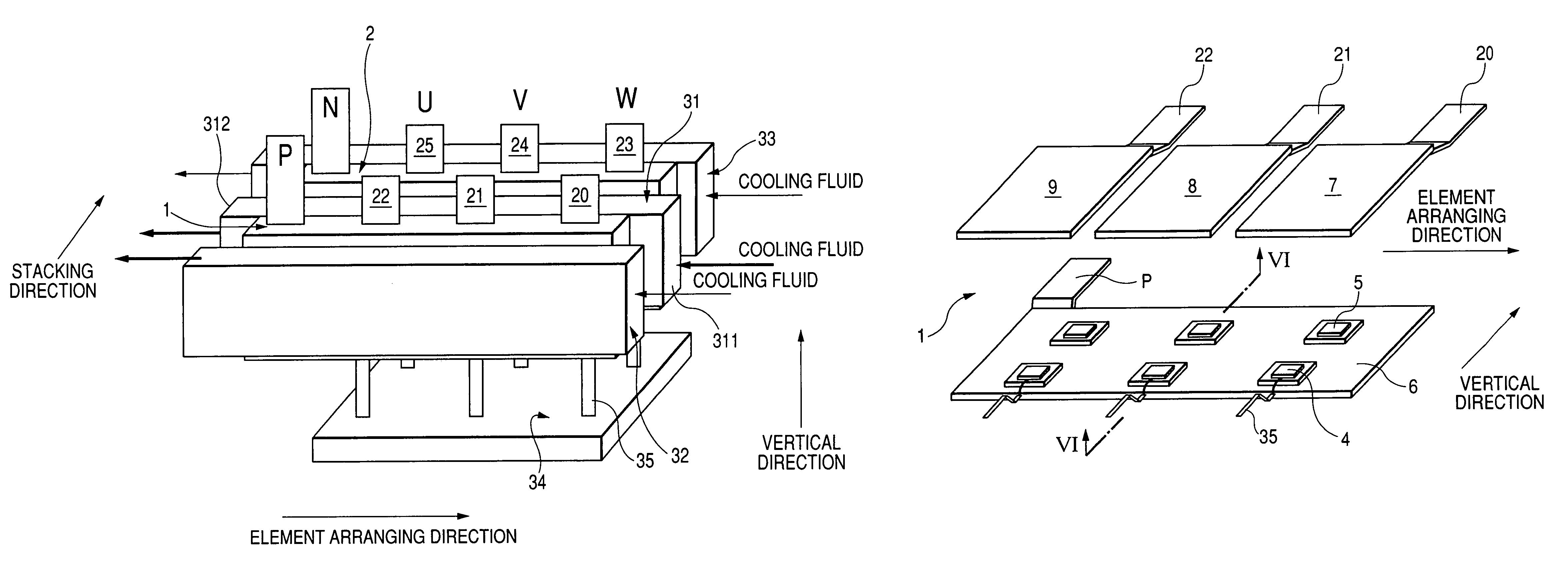
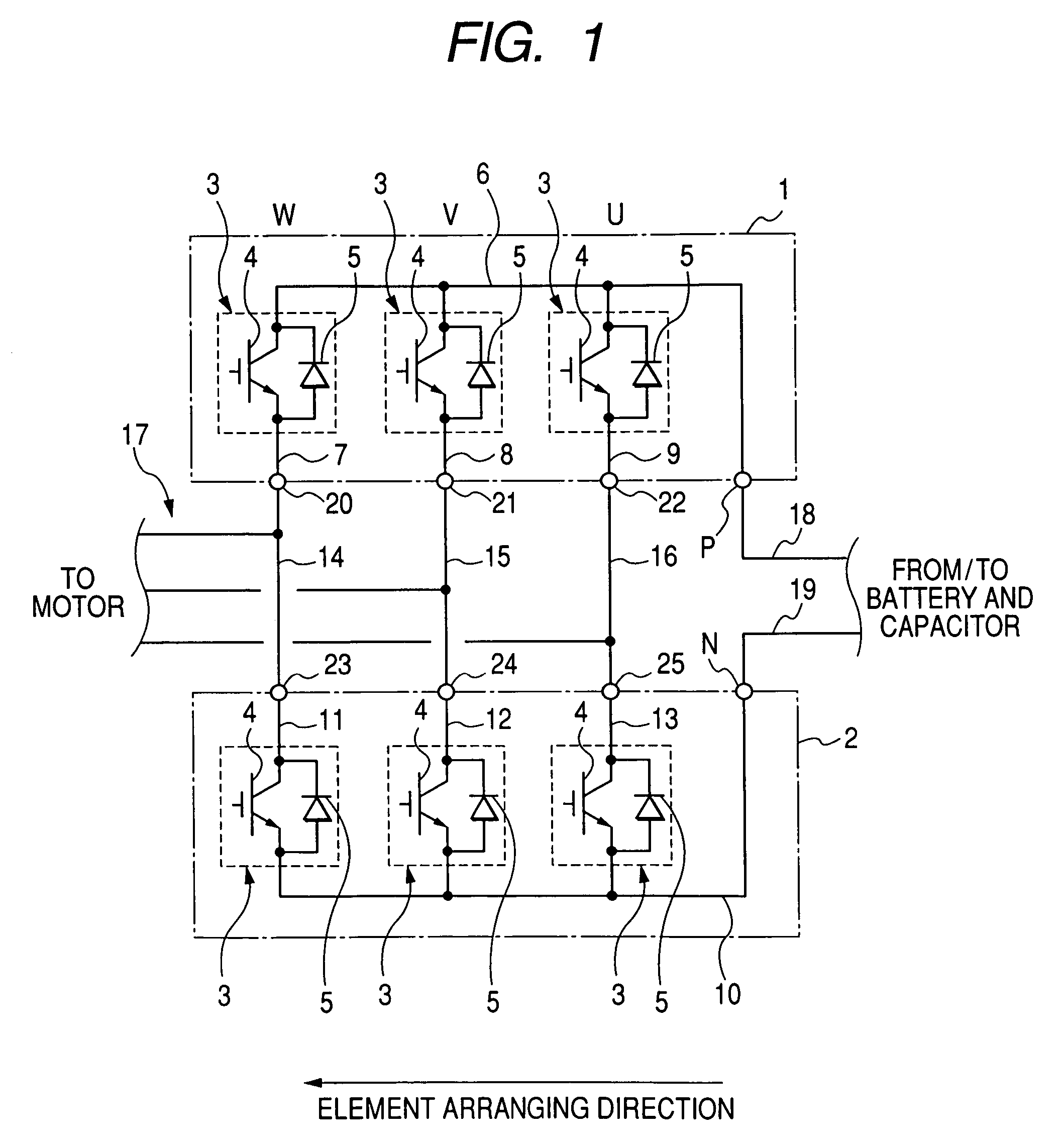
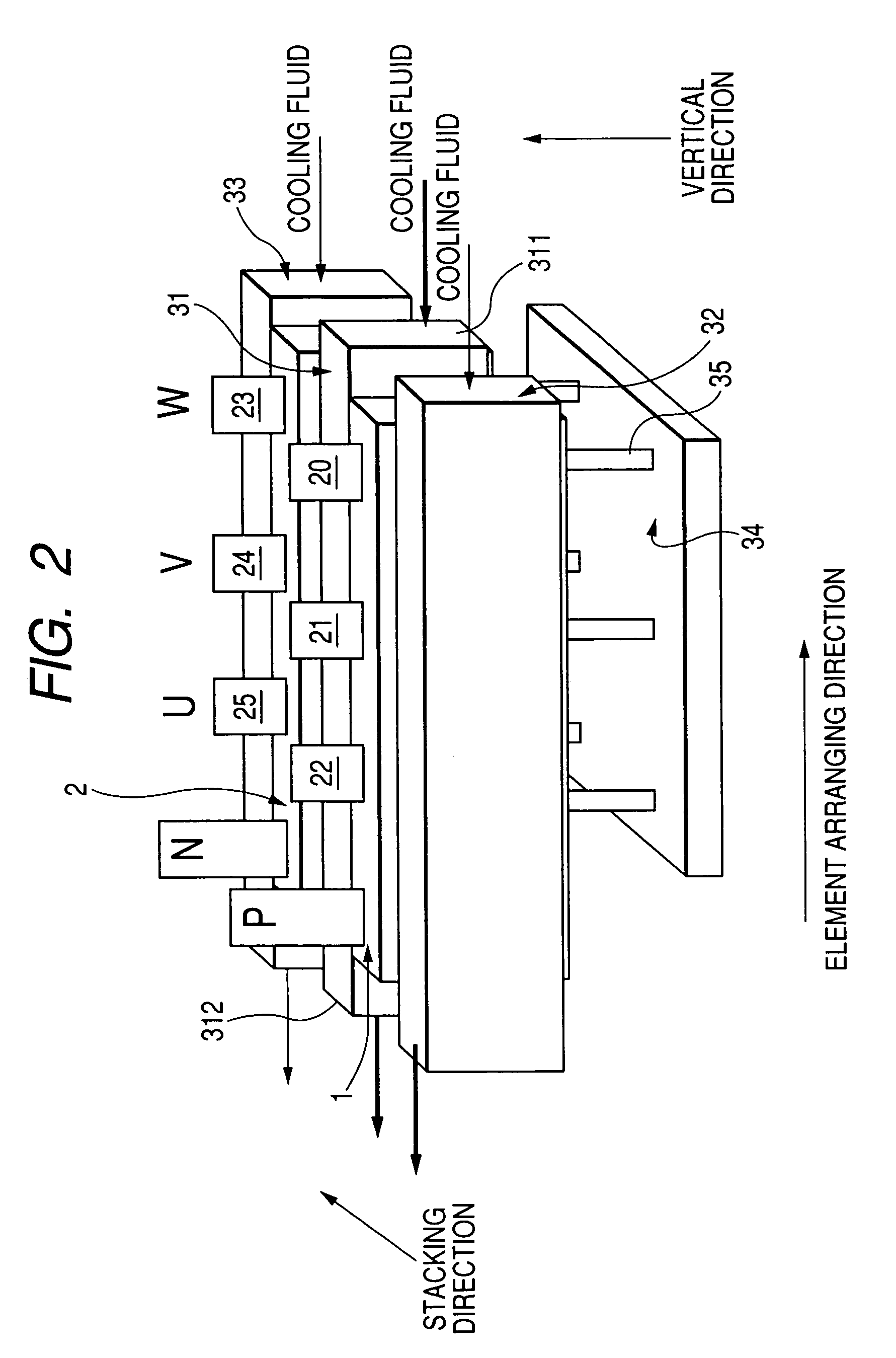
[0044]FIG. 1 is a view showing a circuit of a three-phase inverter representing a multiphase inverter according to the embodiment, and FIG. 2 is a perspective side view schematically showing the inverter shown in FIG. 1.
[0045]As shown in FIGS. 1 and 2, a three-phase inverter has a card shaped upper arm module 1 and a card shaped lower arm module 2. Each of the modules 1 and 2 has an arm element (or current converting element) 3 such as a semiconductor switching element for each of all phases U, V and W. The elements 3 of each module are disposed along an element arranging direction (or first direction) and generate a three phase alternating current from a direct current of a power source (not shown) in cooperation with the elements 3 of the other module. The modules 1 and 2 face each other along a stacking direction substantially perpendicular to the element arranging direction.
[0046]More specifically, the element (called U-phase element) 3 generating a U-phase current of the altern...
modification 1
of the Embodiment
[0082]FIG. 11 is a side view schematically showing the module 1 seen from the module 2 according to a first modification. As shown in FIG. 11, the IGBT chip 4 corresponding to each phase in the module 1 may be disposed to be nearer to the terminal 20, 21 or 22 than the chip 5 of the phase. In this case, the chip 4 of each phase also becomes nearer to the terminal P than the chip 5 of the phase
[0083]Each of the plates 6 to 9 has an electrical resistance (hereinafter, called wiring resistance) for a current flowing through each of the chips 4 and 5, and heat is inevitably generated in the plates 6 to 9 by the currents of the chips 4 to 5 according to the wiring resistances of the plates. The wiring resistance of each plate for a current depends on a path length of the current in the plate. Further, a value of current flowing through the chip 4 of each phase is generally larger than that flowing though the chip 5 of the phase. When the chips 5 are disposed to be nearer...
modification 2
[0087]FIG. 12 is an exploded view of the module 1 according to a second modification, and FIG. 13 is a longitudinal sectional view taken substantially along line XIII-XIII of FIG. 12. As shown in FIGS. 12 and 13, the chips 4 and 5 of each element 3 are disposed adjacent to each other along the arranging direction such that the chips 4 and 5 of the module 1 are aligned with one another along the arranging direction, and the chips 4 are placed to be nearer to the terminals 20 to 22 than the chips 5, respectively. In the same manner, the chips 4 and 5 may be arranged in the module 2.
[0088]Accordingly, as compared with a case where the chips 4 and 5 of each element 3 are disposed adjacent to each other along the vertical direction (see FIG. 5), the length of the inverter along the vertical direction can be shortened. In other words, an aspect ratio of the modules can be lowered, so that the inverter can be easily disposed in a narrow space of the motor.
[0089]As another modification, whe...
PUM
 Abstract
Description
Claims
Application Information
 - R&D
- Intellectual Property
- Life Sciences
- Materials
- Tech Scout
- Unparalleled Data Quality
- Higher Quality Content
- 60% Fewer Hallucinations
Browse by: Latest US Patents, China's latest patents, Technical Efficacy Thesaurus, Application Domain, Technology Topic, Popular Technical Reports.
© 2025 PatSnap. All rights reserved.Legal|Privacy policy|Modern Slavery Act Transparency Statement|Sitemap|About US| Contact US: help@patsnap.com


