Selective scrambler for use in a communication system and method to minimize bit error at the receiver

a communication system and selective scrambler technology, applied in the field of selective scramblers in the communication system, can solve problems such as inter-symbol interference, or isi, loss or incorrect communication of certain bits within the data stream, and skewing in the direct current baselin

Active Publication Date: 2009-12-15
MICROCHIP TECH INC
View PDF14 Cites 13 Cited by
  • Summary
  • Abstract
  • Description
  • Claims
  • Application Information

AI Technical Summary

Benefits of technology

[0014]Even though the preamble and parity sections are coded to eliminate DC accumulation at each frame—and thus at the frame rate (FSY)—relatively long jitter periods can exist in the payload section within a frame and over many frames. The payload is therefore scrambled using a memory device that can capture and hold a sequence of bits. Examples of such a memory device includes random access memory, registers, latches, flip flops, and the like. If a shift register is used, then preferably a linear feedback shift register (or LFSR) can capture the sequence of bits. A LFSR is defined as a shift register having n delay elements, such as D-type flips flops, coupled in series. At least one tap is drawn from the outputs of at least one of the delay elements, and preferable two taps are drawn from two outputs. The taps are fed into an output circuit, and an output of the output circuit is fed back to an input of the first delay element in the sequence.
[0017]A decoder at the receiver can detect the coding violation in the preamble and determine the beginning of each frame and, more particularly, where the payload section and parity section resides relative to each frame. The decoder can also be used to decode the encoded frame, and the decoded bitstream is then forwarded to a descrambler which descrambles the payload. The descrambled payload and the decoded preamble and parity sections, therefore, benefit from a more accurate recovery of the original data stream sent from the source onto the transmission path, absent any bit errors caused by baseline wander or jitter.
[0018]According to one embodiment, the transmitting circuit includes a scrambler. The scrambler can comprise a shift register, an enable circuit, and an output circuit. The shift register may include n stages. The enable circuit can be coupled to the shift register for enabling the shift register to shift in time the sequence of bits within only a payload section of the frame. The output circuit can be coupled to the shift register for preventing the sequence of bits output from the shift register from containing a repeating sequence of the same logic values. The shift register and output circuit with feedback (LFSR) thereby randomizes the sequence of bit values fed to the transmitting circuit and effectively shifts any data dependent jitter upward in frequency so that it can be more effectively removed by the low pass filter within the PLL of a receiving circuit.
[0020]According to yet another embodiment, a method is provided for transferring a sequence of bits. The method includes the steps of substituting a substantially random set of logic values among n bits of a sequence of bits to decrease a jitter period to preferably less than n bits. The method also includes changing the transition period of the substantially random set of logic values to eliminate DC accumulation or baseline wander. The dissimilar logic values and changed transition periods can then be transferred across the transmission medium. Thereafter, the transition period of the n bits can be changed again subsequent to transferring such bits across the transmission medium or path. Similar logic values can thereafter be substituted among the sequence of bits to complete the reconstruction of the coded and scrambled bits prior to being coded and scrambled.

Problems solved by technology

When receiving a data stream that consists of symbols, the transmission path has the effect of widening each symbol in time, thus causing what is known as inter-symbol interference, or ISI.
ISI can result in the loss or incorrect communication of certain bits within the data stream.
For example, sufficient variations in density might cause a skewing in the direct current (DC) baseline seen by a decision circuit located in the receiver.
Thus, the variations in pattern density which create DC accumulation, oftentimes referred to as baseline wander, can cause jitter in the output of the receiver.
Moreover, if the output is used to recover a clocking signal, the jitter will be induced into the sample transitions of the clocking signal to produce bit errors in the recovered data stream.
Even in instances in which there is little if any baseline wander, jitter may still be present in the output data stream.

Method used


Image

  • Selective scrambler for use in a communication system and method to minimize bit error at the receiver
  • Selective scrambler for use in a communication system and method to minimize bit error at the receiver
  • Selective scrambler for use in a communication system and method to minimize bit error at the receiver

Examples


Embodiment Construction

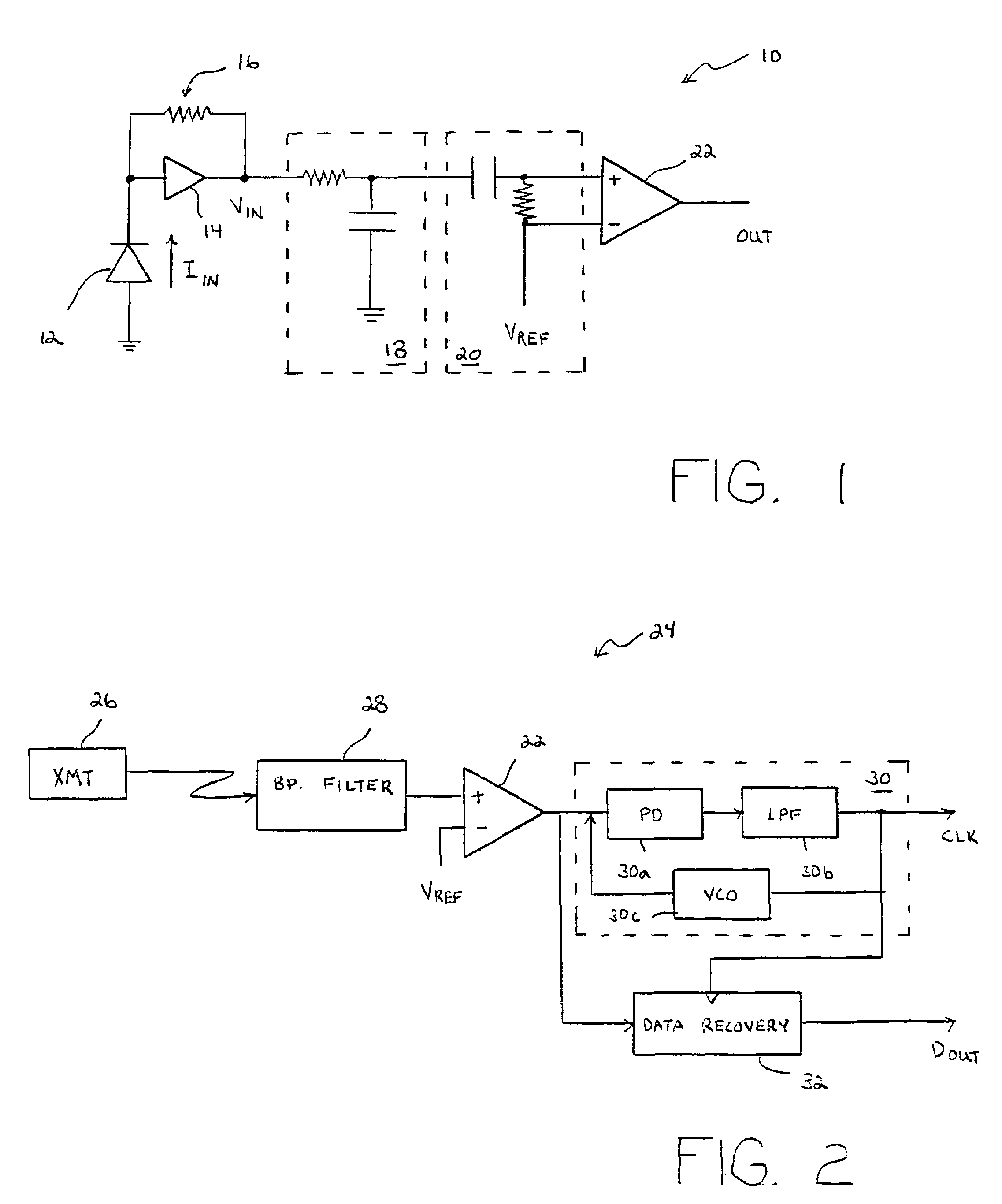
[0042]Turning now to the drawings, FIG. 1 illustrates a receiver 10 that is coupled to receive a data stream sent across a transmission path, such as a wired or wireless transmission path. Receiver 10 can be placed into a node that also contains a transmitter. Each node of the communication system can therefore include a transceiver. If an optical fiber is used, then receiver 10 can convert light energy to an electrical signal upon photosensor 12. Photosensor 12 converts optical energy into electrical energy, such as current IIN. An amplifier or buffer 14 and load resistor 16 convert IIN to an input voltage VIN.

[0043]Associated with the transmission path and / or receiver 10 is a low-pass filter 18. The frequency response of the low-pass filter depends on the resistor and capacitor values within filter 18. Also associated with receiver 10 is a high-pass filter 20. Filter 20 includes a blocking capacitor and a resistor. The resistor produces the voltage across the positive and negative...


PUM


Abstract

A communication system for transmitting and receiving a sequence of bits, and the methodology for transferring that sequence of bits are provided. The communication system includes a transmitting circuit and a receiving circuit. Within the transmitting circuit is a scrambler that comprises a shift register, an enable circuit, and an output circuit. The shift register temporarily stores n bits within the sequence of bits, and the enable circuit enables the shift register to store bits that arise only within the payload section of a frame. The output circuit includes a feedback, and several taps within the n stages to scramble logic values within the sequence of n bits output from the shift registers thus effectively preventing in most instances the sequence of bits from exceeding n number of the same logic value. Within the receiving circuit is a descrambler also having a shift register, an enable circuit, and an output circuit. The descrambler recompiles the scrambled data back to its original form. The scrambler is preferably placed before an encoder in the transmission path to minimize data dependent, low frequency jitter. The encoder is used to place a coding violation into the frame to signal the beginning of each frame, and to encode the parity with an offset against any DC accumulation of the coding violation and the scrambled payload to eliminate all DC accumulation (baseline wander) within each frame.

Description

BACKGROUND OF THE INVENTION[0001]1. Field of the Invention[0002]This invention relates to a communication system and, more particularly, to a scrambler circuit in a transmitter that can randomize the logic values of a sequence of bits within a data stream sent across a transmission path. The scrambler circuit selectively scrambles only a payload section of a frame of bits to minimize low frequency jitter within the data stream and, following scrambling of only the payload, an encoder can be used to encode all sections of the frame to minimize other causes of jitter, such as DC accumulation (or baseline wander) in the data stream.[0003]2. Description of the Related Art[0004]The following descriptions and examples are not admitted to be prior art or conventional by virtue of their inclusion within this section.[0005]A communication system generally contains at least two nodes interconnected by a transmission path. Each node may include both a transmitter and a receiver, generally refe...

Claims


Application Information

Patent Timeline
Patent Type & Authority Patents(United States)
IPC IPC(8): G06F11/00
CPCH04L25/03866H04L1/0061
Inventor GREEN, CHRISTOPHER M.KNAPP, DAVID J.HO, HORACE C.
Owner MICROCHIP TECH INC
Why Eureka
Try Eureka