[0005]An object of the present invention is to provide an improved
hydraulic accumulator that can be used in an economical manner at a reduced production cost and that is characterized by high reliability.
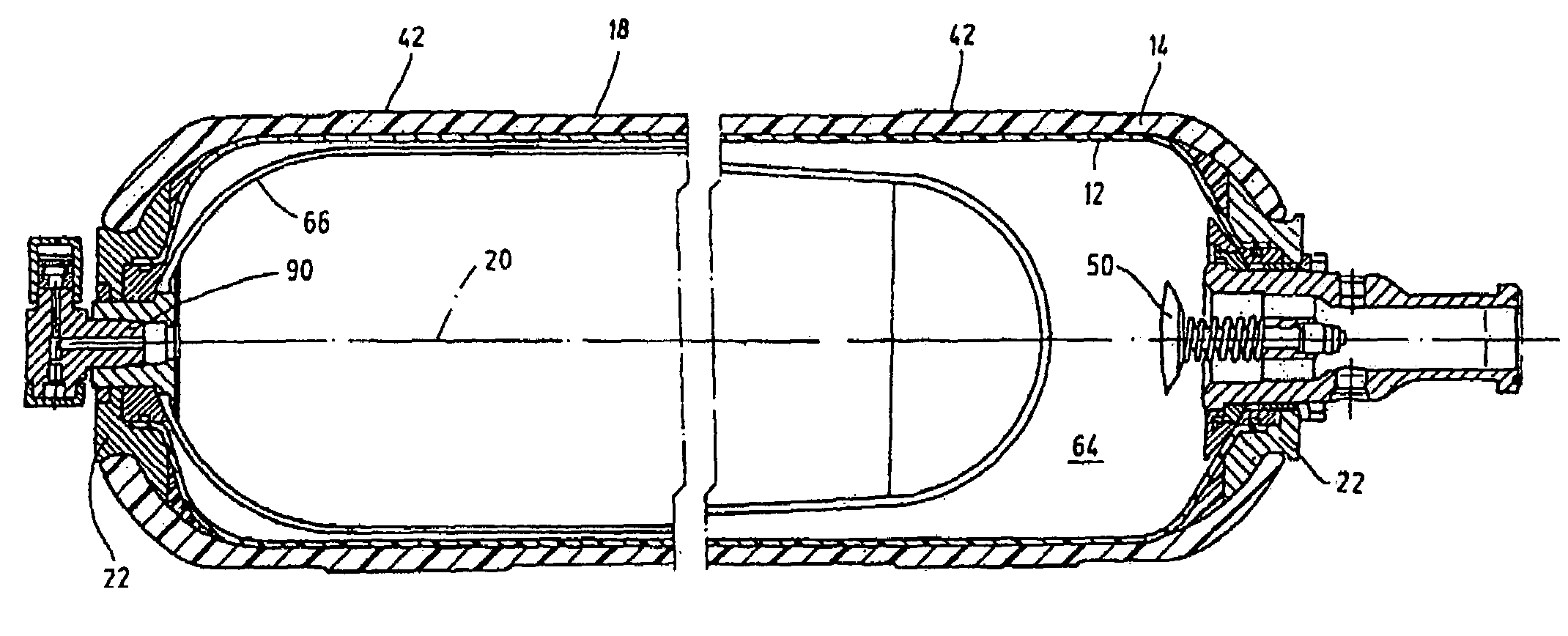
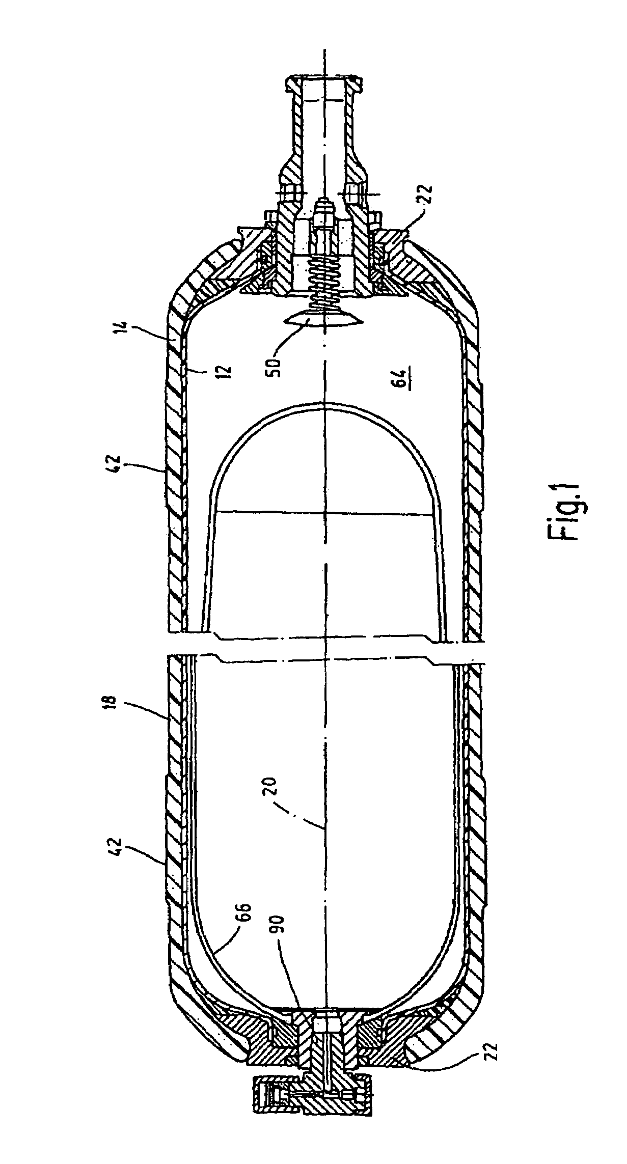
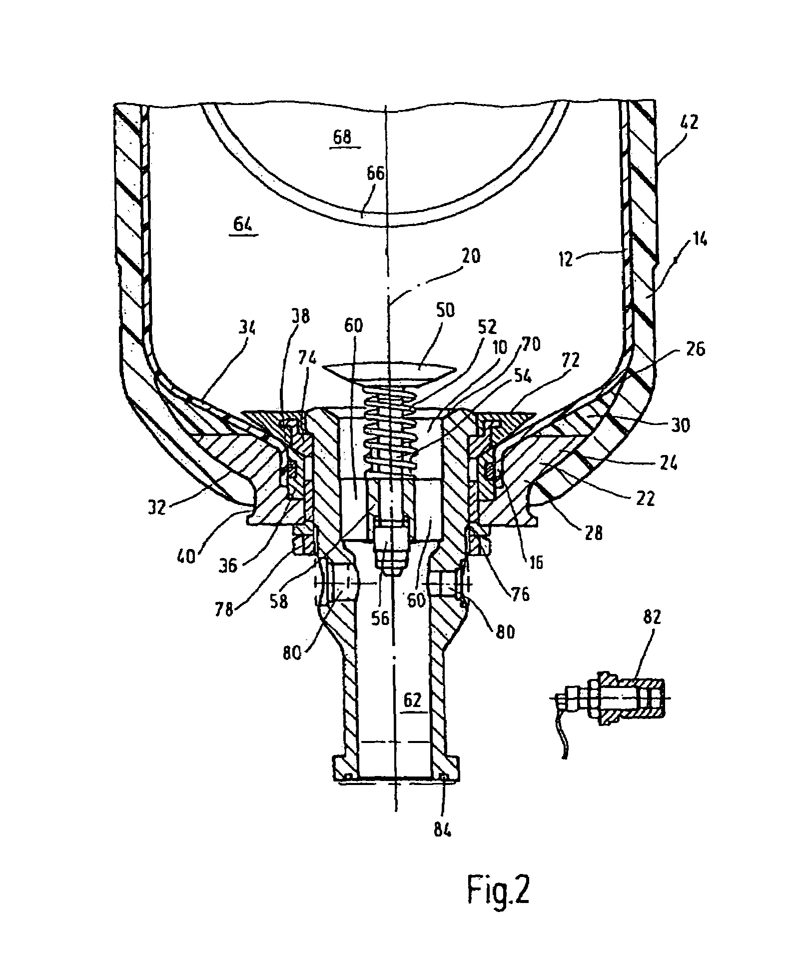
[0006]This object is basically achieved by a hydraulic accumulator where a gap opening between casings is routed as far as the site at which the casings are in contact with one another in a coaxial arrangement, and where triggering the delivery and
discharge of media in the opening is by a valve. A tight accumulator arrangement is then created which can be implemented at low production costs. The hydraulic accumulator according to the present invention can be used for a plurality of applications. In that support takes place as far as into the outer
peripheral region of the two casings by an outside support ring tapering in the manner of a wedge, relative movements which may occur between the plastic casings are accommodated by the outside support ring. Damaging
delamination processes directly between the susceptible
plastic materials are avoided. Furthermore, in this way stable and reliable support for the disk valve in the opening region of the pressurized container is created so that it is possible for the first time to use accumulators which are made entirely of plastic
layers for bladder-hydraulic accumulator solutions and which are built with an extremely large volume. Furthermore, standard
plastic materials, for example, in the form of
polymer materials, can be used due to the wedge-like intermediate support for the plastic casings. This use helps
cut production costs.
[0007]The contour surfaces of the first and second plastic casing facing one another can be implemented based on the wedge-like routing of the outside support ring leading into the outer
peripheral region of the arrangement without sharp deflections and without sudden changes of direction. This structure enables especially careful application of force for the plastic casings. The application of force is especially favorable when the outside support ring is made in one piece and of a plastically deformable plastic material, especially of a
polymer material.
[0008]Good results can, however, also be achieved when the outside support ring as a rigid support part body is composed of at least two individual segments, for example, in the manner of individual rings. This two-segment arrangement simplifies production, and accordingly helps reduce production costs. The outside support ring, to the extent it supports the collar part of the liner, can here be made of a
metal material. The wedge-like tapering region between the plastic casings can be of a plastic material, for example, in the form of a plastically deformable buffer ring of
polymer material. Depending on the production process, this plastically deformable plastic can also be injected or cast into the defined gap. If the buffer ring or the outside support ring as a whole is of a plastic material, this arrangement leads to a significant reduction of weight. This weight reduction increases the possible applications of the hydraulic accumulator, for example, in the field of aeronautics and space travel. Furthermore, as a result of the plastic configuration for the outside support ring or parts of it, it can be ensured that the plastic material on the casings will not be damaged on the sharp-edged transition sites. For a
metal, individual ring-segment design, also for the buffer ring,
high stiffness for the container arrangement can be established, so that depending on the application the hydraulic accumulator can be modularly produced according to requirements.
[0010]In another preferred embodiment of the hydraulic accumulator according to the present invention, the outside contour of the outside support ring in the direction of the gap opening is provided with a convex curvature. Its opposite inside contour, proceeding from the gap opening, can extend in a straight slope which at the site of the entry of the collar part ends in a contact surface parallel to the longitudinal axis of the container. This configuration of the outside support ring with a convex curvature on the outside contour and a plane-parallel configuration on the inner contour side leads to especially favorable application of force of the loads of the inner casing into the outside support ring which in this respect is further supported by the outer plastic casing by winding.

