
Apparatus and method for performing in-vitro DNP-NMR measurements

a technology of in-vitro dnpnmr and apparatus, which is applied in the field of apparatus and methods for performing invitro dnpnmr measurements, can solve the problems of wide commercial application of nmr (nuclear magnetic resonance) spectroscopy that has been somewhat restricted, the inherent low sensitivity of the technique, and exceptionally costly solutions, so as to minimise the loss of polarisation, minimise the reaction force, and reduce the effect of stray or external fring

Inactive Publication Date: 2009-12-29
OXFORD INSTR NANOTECH TOOLS
View PDF5 Cites 26 Cited by
  • Summary
  • Abstract
  • Description
  • Claims
  • Application Information

AI Technical Summary

Benefits of technology

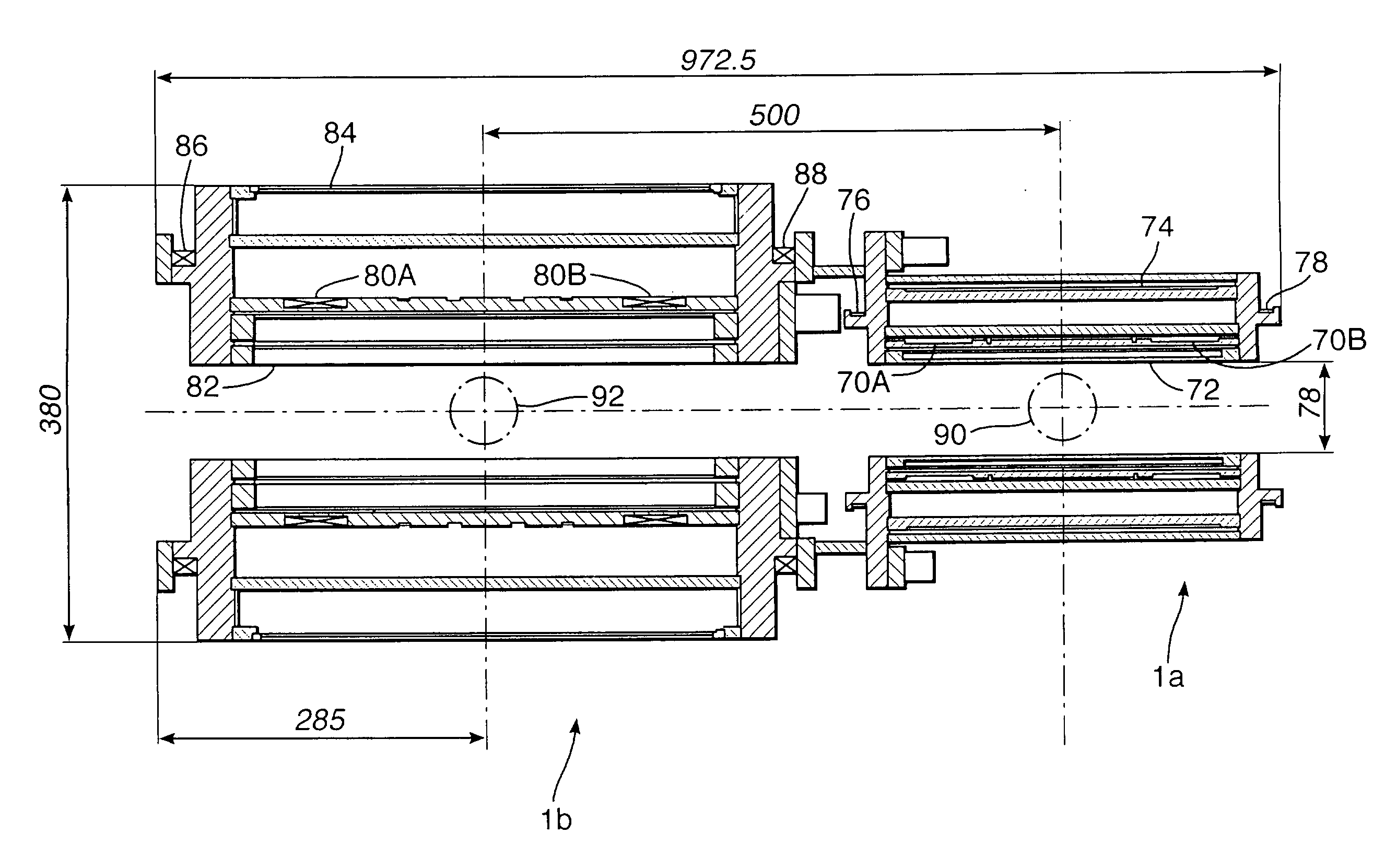
[0034]We have realised that it is important to locate the two working regions as close together as possible so as to minimise loss of polarisation etc. This can be achieved using a single magnet assembly, suitably structured, or a pair of magnet assemblies located in the cryostat and surrounding respective, coaxial bores so as to define the corresponding NMR and DNP working regions in the bores, wherein the magnet assemblies are suitably shielded so that the magnetic field in the DNP working region has a homogeneity or profile suitable for performing DNP on the sample and the magnetic field in the NMR working region has a homogeneity or profile suitable for performing a NMR process on the sample. In the latter case, despite the fact that high field strengths are required within the working regions, it is possible to locate the two magnet assemblies close together by the use of suitable shielding. In particular, the use of suitable shielding minimises the reaction forces between the magnet assemblies, the influence of the stray or external fringe field from one magnet assembly on the magnitude of the central field of the other, and the influence of the gradients within the stray or external fringe field from one magnet assembly on the field uniformity (homogeneity) of the other.
[0035]Two shielding methods are available, passive by means of ferromagnetic material or active by means of reverse energised coil sets positioned within the individual magnet coil assemblies so as to reduce the stray or external fringe field from the main magnet. These coils can be considered to shape the fringe fields that exist between two (or more) magnets in close proximity so as to reduce the magnetic influence one on the other. Active shielding is preferred because it reduces the weight of the assemblies and can shield a variety of fields generated by the magnet assemblies.
[0036]We have found, in particular, that in order to reduce the influence of the two magnet assemblies on each other, in most cases active, end shielding coils should be provided. End shielding coils have most influence close to the magnetic axis and act over relatively short axial distances. In contrast conventional outer shielding coils act over regions more remote from the magnet. The combination of end and outer shielding coils, when correct combinations are applied significantly reduces the stray field.
[0040]An important aspect of the present invention is that the sample can be moved from the cold polarizing region to a relatively warmer (preferably room temperature) region before dissolution. Hence the sample is moved whilst frozen. As described above, a significant proporation of the hyperpolarization will be retained if the sample is kept cold and within a relatively strong magnetic field (>0.1 T), and is moved quickly (˜seconds). This is the case in the preferred embodiment of the present invention (in which the sample moves through a minimum field of ˜0.3 T between the two magnets).
[0042]In order sufficiently to cool the sample in the DNP working region, preferably the apparatus further comprises coolant such as liquid helium in the bore defining the DNP working region. This allows the sample to be very closely surrounded by liquid helium and thus its temperature reduced close to that of the liquid helium.

Problems solved by technology

The widespread commercial application of NMR (nuclear magnetic resonance) spectroscopy has been somewhat restricted by the inherent low sensitivity of the technique.
NMR signal increases with magnetic field strength, which is one of the reasons behind the trend for development of ever higher field magnets, but this is an exceptionally costly solution to improved SNR.
Several techniques for achieving hyperpolarization have been reported, but most have technical restrictions which limit their application to specific niche markets (e.g.: hyperpolarized 129Xe gas lung imaging).
However, in the apparatus described in that paper, there is a significant delay and variability caused by the manual transfer of the liquid sample from the polarizing apparatus to the NMR magnet.
However, this is impractical for several reasons:the amp-tums required to locally shim the fringe field cannot be generated by a conventional superconducting shimthe forces generated between a superconducting shim and the main magnet would be unacceptablethe superconducting shim would destroy the homogeneity of the NMR field region.
However, U.S. Pat. No. 6,515,260 does not describe how to achieve this apparatus in practice, i.e.: how to generate two uniform magnetic field regions in close proximity.

Method used


Image

  • Apparatus and method for performing in-vitro DNP-NMR measurements
  • Apparatus and method for performing in-vitro DNP-NMR measurements
  • Apparatus and method for performing in-vitro DNP-NMR measurements

Examples


Embodiment Construction

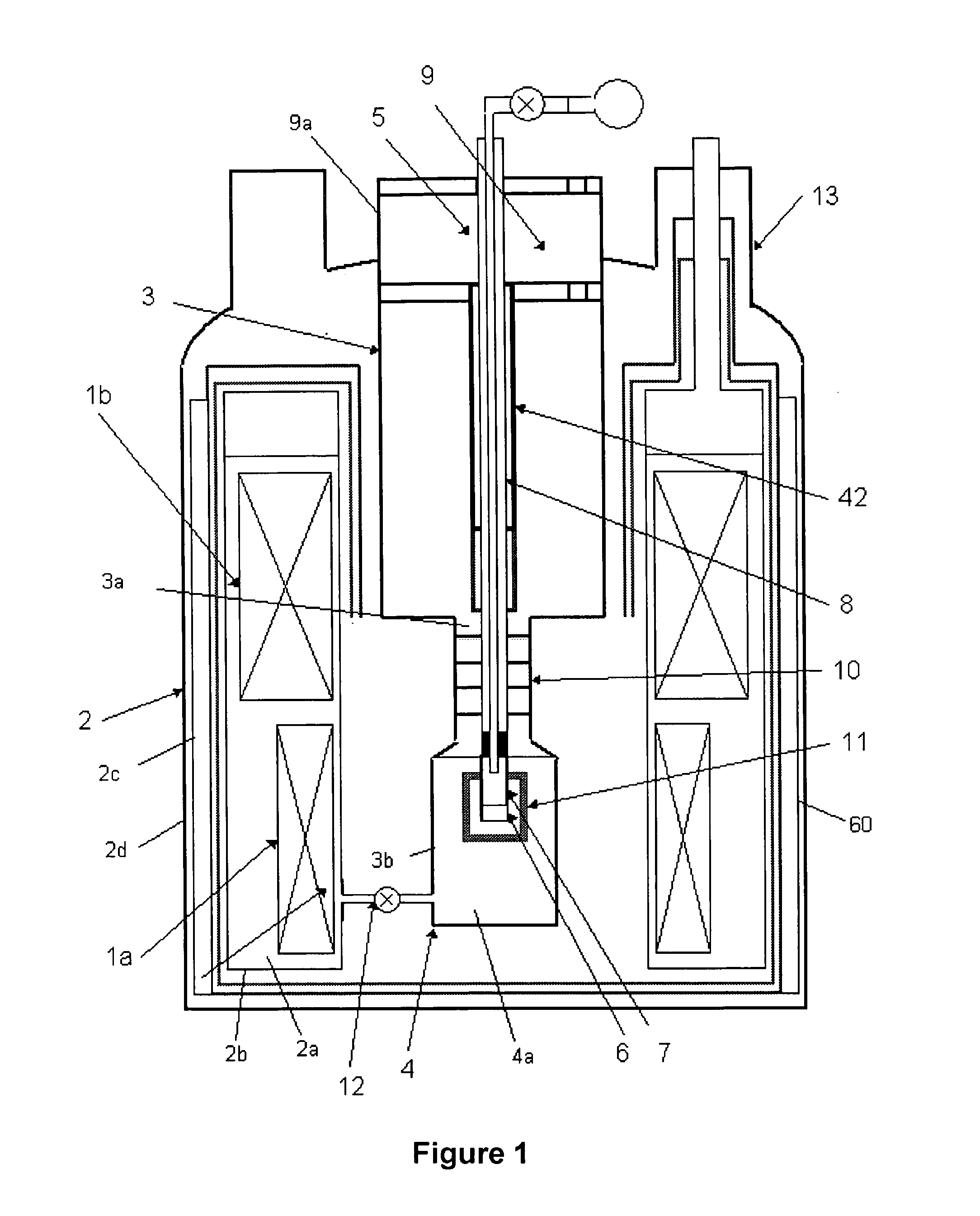
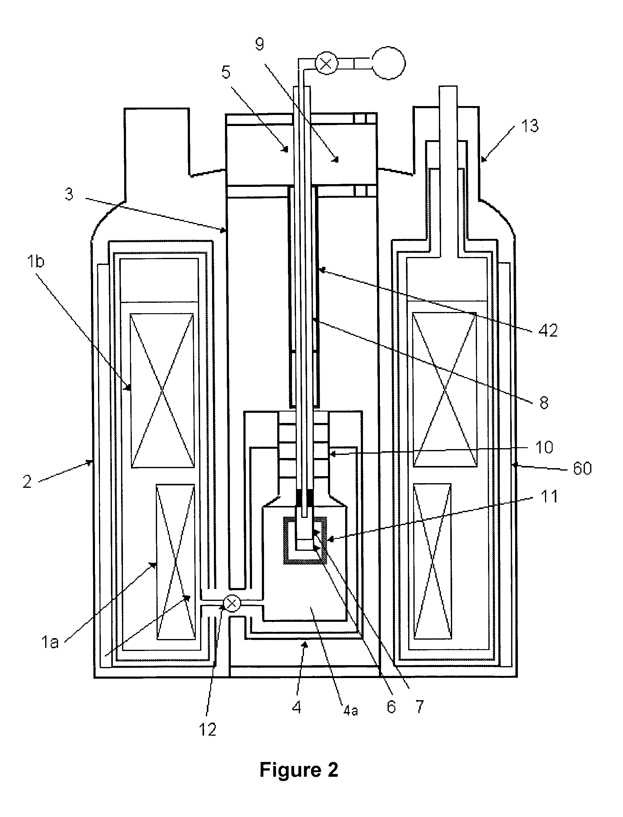
[0055]Referring to FIG. 1, the combined DNP-NMR apparatus comprises a polarizing magnet 1a, positioned below an NMR magnet 1b, inside a cryostat 2, having a room temperature bore 3 containing an access port 3a to a polarization chamber 4 within a coaxial bore 3b. A sample positioning assembly 5 is located in the bores 3,3b. This comprises a container 7 in which a sample 6 is located, the container being attached to the end of a positioning rod 8. The rod may be moved vertically within the bores to position the sample within the polarization chamber 4, an NMR RF probe 42, or to remove it from the bores into a sample changer apparatus 9. It will be recognised that other orientations of the magnets are possible.

[0056]The cryostat 2 is of conventional form and has an inner Helium can 2a surrounded by a radiation shield 2b, a nitrogen can 2c and an outer vacuum wall 2d.

[0057]When the sample is in the polarization chamber 4 it is immersed in liquid helium 4a. The polarization chamber has...


PUM


Abstract

Apparatus for performing in-vitro DNP-NMR measurements on a sample comprises magnetic field generating apparatus (1a, 1b) located in a cryostat (2) and surrounding a bore defining respective NMR and DNP working regions (90, 92). A system for performing DNP on a suitably prepared sample in the DNP working region. A system for performing a NMR process on a sample in the NMR working region. A sample positioning mechanism (5) which can be inserted in the bore (3) to bring a sample in turn into each of the working regions. The magnetic field generating apparatus is suitably structured so that the magnetic field in the DNP working region has a homogeneity or profile suitable for performing DNP on the sample and the magnetic field in the NMR working region has a homogeneity or profile suitable for performing a NMR process on the sample.

Description

FIELD OF INVENTION[0001]The invention relates to apparatus and methods for performing in-vitro DNP-NMR measurements on a sample.BACKGROUND[0002]The widespread commercial application of NMR (nuclear magnetic resonance) spectroscopy has been somewhat restricted by the inherent low sensitivity of the technique. This is particularly true for 13C and 15N nuclei, due to their low magnetic moments and natural abundance compared to 1H. The signal to noise ratio (SNR) of NMR may be improved by reducing thermal noise or enhancing signal. The former approach has recently seen increased use through the widespread commercial availability of cryogenically cooled RF probes, despite the fact that it only affords a SNR gain of perhaps a factor five under ideal circumstances. NMR signal increases with magnetic field strength, which is one of the reasons behind the trend for development of ever higher field magnets, but this is an exceptionally costly solution to improved SNR.[0003]An alternative meth...

Claims


Application Information

Patent Timeline
IPC IPC(8): G01V3/00G01R33/30G01R33/46G01R33/62
CPCG01R33/30G01R33/62G01R33/46
Inventor HUTTON, GRAHAM MARKSLADE, ROBERT ANDREWBROWN, FRANCIS JOHN
Owner OXFORD INSTR NANOTECH TOOLS
Learn More