RF receiver utilizing dynamic power management

a technology of dynamic power management and rf receiver, which is applied in the direction of radio transmission, amplifiers, electrical equipment, etc., can solve the problems of high power consumption, low power efficiency, and the majority of receivers, especially those fielded on ground vehicles or aircraft, will spend a significant amount of time in benign interference environments, so as to reduce the overall power consumption and thermal load of rf receiver, reduce the maximum power, and degrade the reception of the desired signal

Active Publication Date: 2009-12-29
ROCKWELL COLLINS INC
View PDF22 Cites 26 Cited by
  • Summary
  • Abstract
  • Description
  • Claims
  • Application Information

AI Technical Summary

Benefits of technology

[0015]In a highly preferred embodiment, a first power sensor is associated with an input of the A1 for coupling the full band RF signals; a second power sensor is associated with an input of the M1 for coupling the sub-band RF signals; and, a third power sensor is associated with an input of the M2 for coupling the wide band IF signals. Each of the power sensors has a threshold setting unique to its location in the system, the unique threshold setting for each power sensor is set to a level just below a total RF power level where desired signal degradation may occur. An output of the digital processing (DSP) subsystem sent to the control logic subsystem is utilized to determine if a significant portion of a total power sensed at each power sensor is a desired signal. The output of the digital processing subsystem sent to the control logic subsystem is also utilized to serve as a power sensor for narrow band IF signals after the second IF filter (F4). A control logic subsystem operatively associated with the power sensors and the digital signal processing subsystem detects an interference environment based on their outputs and determines its bias outputs accordingly. The bias outputs of the control logic subsystem are fed to the RF amplifier (A1), the first IF amplifier (A2), the secondary IF amplifiers (A3 and A4), and the local oscillators (LO1 and LO2) to control their power consumptions to reduce overall power consumption and thermal load of the RF receiver. Thus, the IP3 performance of the RF receiver is dynamically adjusted based on an interfering environment that it is operating within.
[0016]The full power of the dynamic power management aspect of the RF receiver of the present invention is only utilized when an interfering signal is actually present on the receiver input and has a potential for degrading a reception of a desired signal. The present invention further takes advantage of the filtering already in the receiver to provide power control on a stage by stage basis. The present invention, while it does not reduce the maximum power needed to operate a RF receiver, can significantly decrease the average power needed. When the present invention is considered in a multi-channel receiving system such as the Joint Tactical Radio System (JTRS) with individual receive channels spread over a wide range of frequencies, the average power saving can become substantial. Maximum power on all channels simultaneously will occur only rarely. This significant reduction in average power consumption translates to a lower overall system thermal load and increased reliability.

Problems solved by technology

Current art for radio frequency (RF) receivers operating in a high interference or co-site environment generally take one of two approaches, both of which are expensive and dissipate high power:a) Operate a receiver front end and intermediate frequency (IF) components at very high IP3 levels, i.e. utilize high powered components so that distortion does not occur; and,b) Add additional hardware outside the receiver volume such as high performance filters, or active canceling circuitry.
Filtering has a restricted area of benefit and active canceling is extremely expensive and has specific demands on the host vehicle's antenna architecture.
However, most receivers, especially those fielded on mobile platforms such as ground vehicles or aircraft will spend a significant amount of time in benign interference environments.
While operating in benign environments, the high power applied to achieve high IP3 performance is wasted.
This wasted power increases the operating temperature of receiving system with a corresponding reduction in its reliability.
In the system illustrated in FIG. 1, there is no way to estimate the level of interference that may be occurring within the receiver since only the DSP has any knowledge of the desired signal integrity.
The DSP has no way of determining that the desired signal was degraded elsewhere in the receiver.
As a result, while operating in benign environments, the high power applied to achieve high IP3 performance is wasted.
This wasted power increases the operating temperature of the receiver with a corresponding reduction in its reliability.

Method used


Image

  • RF receiver utilizing dynamic power management
  • RF receiver utilizing dynamic power management
  • RF receiver utilizing dynamic power management

Examples


Embodiment Construction

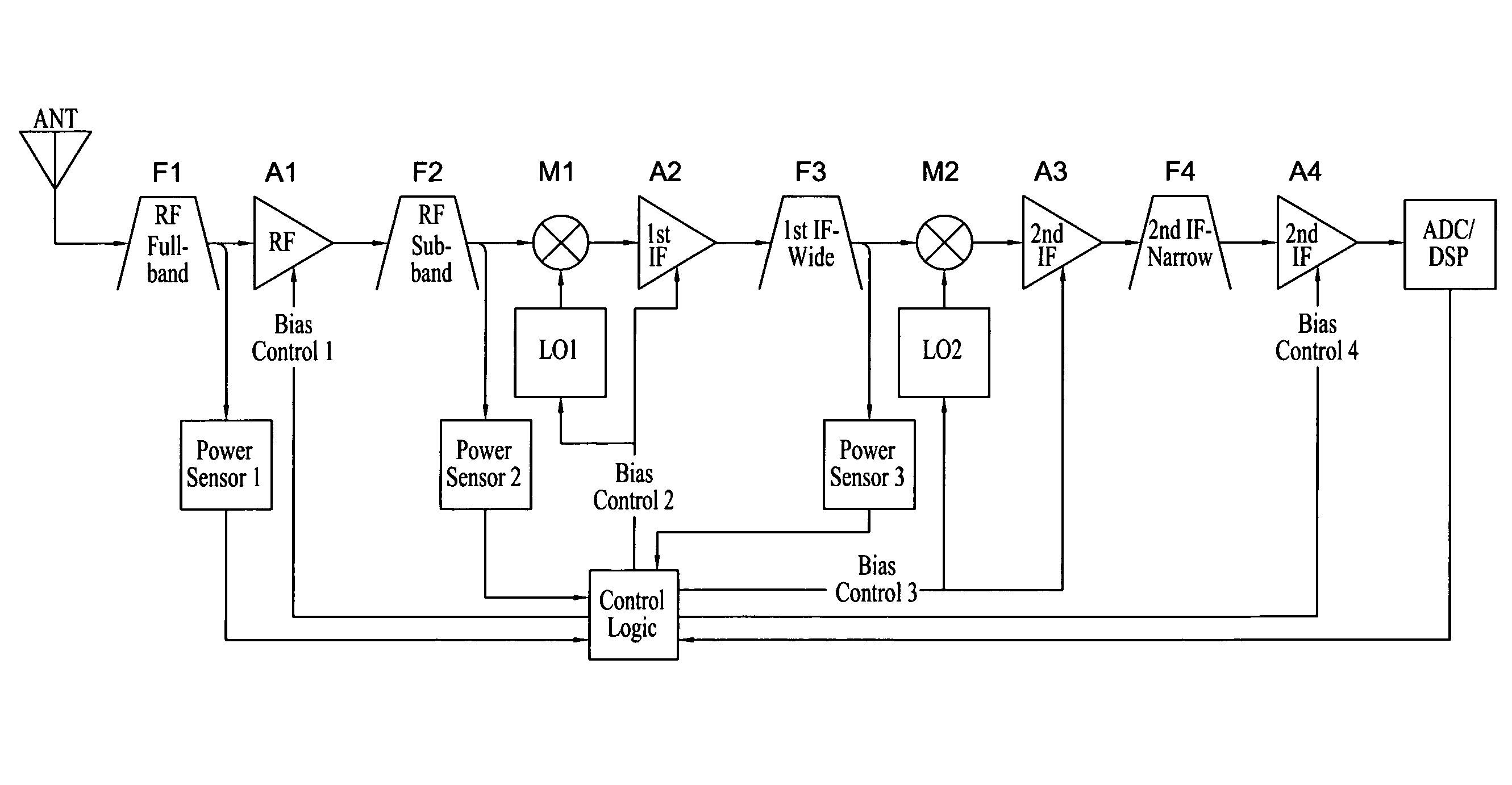
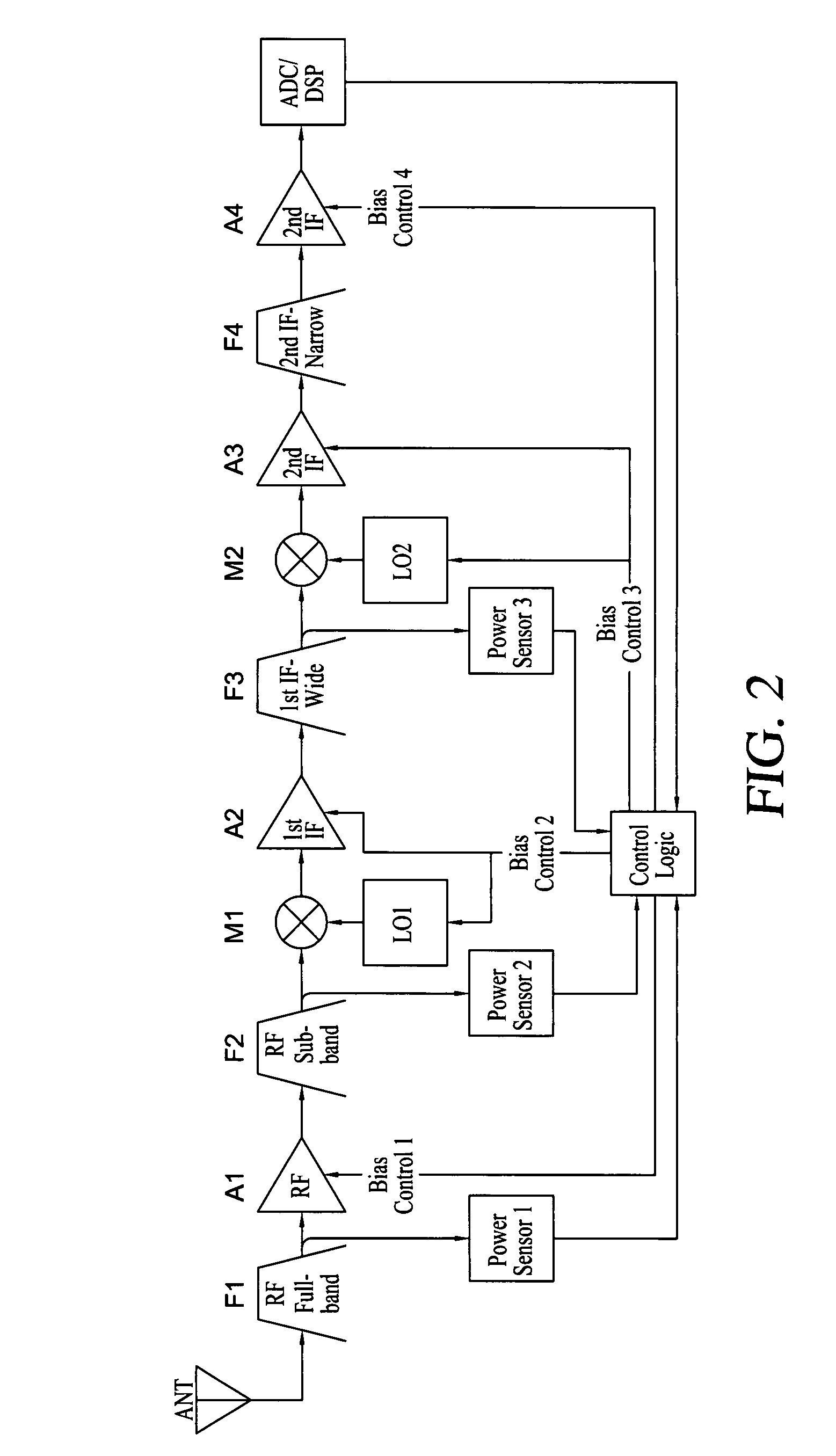
[0019]Referring now to FIG. 2, a preferred embodiment of a radio frequency (RF) receiver utilizing dynamic power management for administration of power consumption in accordance with the principles of the present invention is illustrated. The RF receiver includes an antenna (ANT) that receives RF signals in a high interference and / or co-site environment. An RF full band filter (F1) filters the received RF signals from an output of the ANT to filtered full band RF signals. The F1 may have, for example, for the purposes of illustration but not limitation, a bandwidth of approximately 1 GHz.

[0020]An RF amplifier (A1) amplifies the filtered full band RF signals to enlarged full band RF signals suitable for RF sub-band filtering. The A1 has programmable bias points (BiasControl1) with a gain of, for example, approximately 10 dB.

[0021]An RF sub-band filter (F2) filters the enlarged full band RF signals to sub-band RF signals. The F2 may have a bandwidth of, for example, approximately 100 ...


PUM


Abstract

A radio frequency (RF) receiver utilizing dynamic power management for administration of power consumption. The RF receiver includes an RF antenna, an RF full band filter, an RF amplifier, an RF sub-band filter, a first local oscillator, an RF mixer, a first IF amplifier, an IF wide band filter, a second local oscillator, an IF mixer, two secondary IF amplifiers, an IF narrow band filter, a digital signal processing subsystem, three power sensors, and a control logic subsystem. Based on its location in the system, each power sensor has a unique threshold setting that is set just below a total RF power level where desired signal degradation might occur. The control logic subsystem utilizes outputs of the power sensors to detect a total RF power present due to interfering signals plus a desired signal within an entire bandwidth present at each stage and dynamically manages power by adjusting bias of each stage accordingly via its bias control outputs.

Description

BACKGROUND OF THE INVENTION[0001]1. Field of the Invention[0002]The present invention relates generally to techniques for reducing power consumption of radio frequency receivers and more specifically to methods and apparatus for dynamically managing power consumption of radio frequency receivers operating in interference environments via environment sensing.[0003]2. Description of the Related Art[0004]Current art for radio frequency (RF) receivers operating in a high interference or co-site environment generally take one of two approaches, both of which are expensive and dissipate high power:[0005]a) Operate a receiver front end and intermediate frequency (IF) components at very high IP3 levels, i.e. utilize high powered components so that distortion does not occur; and,[0006]b) Add additional hardware outside the receiver volume such as high performance filters, or active canceling circuitry. Filtering has a restricted area of benefit and active canceling is extremely expensive and...

Claims


Application Information

Patent Timeline
Patent Type & Authority Patents(United States)
IPC IPC(8): H04B1/16
CPCH03F1/0272H03F1/0266
Inventor HALVORSON, DAVID H.
Owner ROCKWELL COLLINS INC
Why Eureka
Try Eureka