
Plasma etching equipment

a technology of etching equipment and plasma, which is applied in the direction of coatings, electric discharge lamps, electric lighting sources, etc., can solve the problems of reducing affecting the selectivity of sufficiently high masks, and affecting the quality of plasma etching, so as to reduce the degree of etching. , the effect of reducing the deviation of the profil

Inactive Publication Date: 2010-01-19
ROBERT BOSCH GMBH
View PDF17 Cites 17 Cited by
  • Summary
  • Abstract
  • Description
  • Claims
  • Application Information

AI Technical Summary

Benefits of technology

[0006]The plasma etching system according to an exemplary embodiment of the present invention may provide that in the upper part of the reactor chamber, which may be used as a second plasma-generating device, in the case of a process according to German Published Patent Application No. 42 41 045, a high-density plasma may be generated, having a high density of etch species and passivation species and excessively high ion densities and undesirable plasma potential interruptions and inhomogeneities in the initially produced second plasma may be removed so that, in passing through the first gas feed which in particular may be simultaneously used as a discharge device, these ions at least may largely recombine with electrons, so that the ion density of the reactive gas supplied to the downstream first plasma-generating device may be virtually zero or may be negligible. Thus, density inhomogeneities and potential inhomogeneities may be also eliminated.

Problems solved by technology

However, an undesirable ion density may appear in such processes along with a desired increase in the fluorine radical density and these ions may interfere with the actual etching process and may be detrimental to a sufficiently high mask selectivity.
These ions heat up the wafer to be etched, resulting in profile deviations.
The portion of the high frequency power injected into the plasma which was used to generate an undesirably high ion density may be lost here in the form of heat or radiation.
Although other prior devices for the reduction of the ion density may be successful, in practice there may still appear, in particular in the margin area of the substrate to be etched, profile deviations, profile asymmetries, etching rate excesses, or regular or irregular profile undercuts, which may be referred to as “beaking” effects and which may not be tolerable in many applications.
In other prior devices for the reduction of the ion density it may be a problem in particular that an ion density in excess by one to two orders of magnitude may be required to be applied completely homogeneously to the desired area over the entire surface to be etched, having, for example, a diameter of 150 mm or 200 mm, without thereby causing distortions of the plasma potential on the surface of the substrate to be etched.
Due to such distortions of the plasma potential, excessive local ion densities and / or excessive local ion energies may result there in the above-mentioned detrimental effects.

Method used


Image

  • Plasma etching equipment
  • Plasma etching equipment

Examples


Embodiment Construction

[0031]The present invention is first directed to a plasma etching system, in principle referred to in German Published Patent Application No. 199 00 197, which is modified, as is explained below.

[0032]By using this modified plasma etching system, an anisotropic plasma etching process for silicon may be subsequently performed, as is discussed in German Published Patent Application No. 42 41 045.

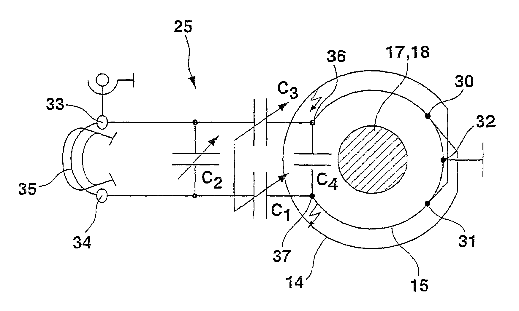
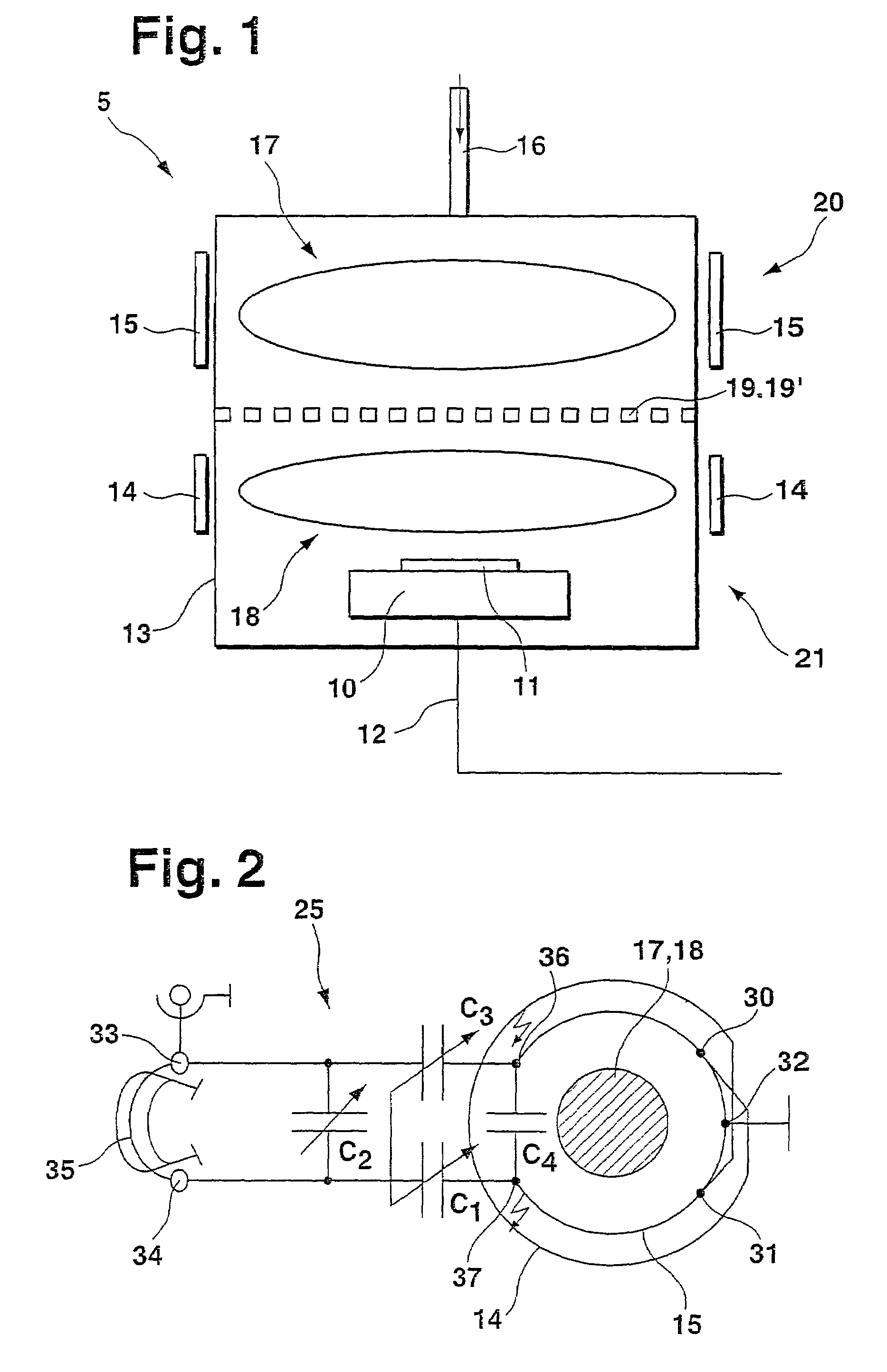
[0033]In particular, plasma etching system 5 according to FIG. 1 has a reactor chamber 13, which is divided into two approximately even-sized areas by a discharging device 19′, which are assigned to a first plasma-generating device 21 in the lower part of reactor chamber 13 and to a second plasma-generating device 20 in the upper part of reactor chamber 13. Furthermore, reactor chamber 13 has a second gas feed 16 to a second plasma-generating area 17 and a first gas feed 19 to a first plasma-generating area 18.

[0034]First gas feed 19 is configured in the form of a metallic mesh which reduces t...


PUM

PropertyMeasurementUnit
Fractionaaaaaaaaaa
Fractionaaaaaaaaaa
Pressureaaaaaaaaaa

Abstract

A plasma etching system for etching, in particular anisotropic etching, of a substrate by using a plasma. The plasma etching system has a first plasma-generating device which is inductively coupled in particular and has a first arrangement for generating a first high-frequency electromagnetic alternating field, a first plasma-generating area for generating a first plasma and a first gas feed, as well as a first plasma-generating device downstream from a second plasma-generating device which is inductively coupled in particular and has a second arrangement for generating a second high-frequency electromagnetic alternating field, a second plasma-generating area for generating a second plasma and a second gas feed. The substrate to be etched is arranged in the first plasma-generating device. The second plasma is suppliable to the first plasma-generating device via the first gas feed at least partially as a first reactive gas.

Description

FIELD OF THE INVENTION[0001]The present invention relates to a plasma etching system in particular for anisotropic etching of a substrate using a plasma.BACKGROUND OF THE INVENTION[0002]A silicon high-rate etching process where silicon is etched using inductive plasma excitation is discussed in German Published Patent Application No. 42 41 045. To achieve as high as possible etching rates it may be required to provide an as high as possible concentration of fluorine radicals in the plasma produced. This may occur via irradiation of an appropriately high high-frequency power, having power values between 3 and 6 kW, into the inductive plasma source under simultaneously increased process pressure of 30 to 100 μbar, or up to 250 μbar if the required uniformity of the plasma produced permits this. However, an undesirable ion density may appear in such processes along with a desired increase in the fluorine radical density and these ions may interfere with the actual etching process and m...

Claims


Application Information

Patent Timeline
IPC IPC(8): H01L21/306C23C16/00H01L21/3065H01J37/32H01L21/00
CPCH01J37/321H01J37/32183H01J37/32357H01L21/67069
Inventor LAERMER, FRANZSCHILP, ANDREA
Owner ROBERT BOSCH GMBH
Learn More