
Electrode material and fuel cell

a fuel cell and electrode technology, applied in the direction of cell components, basic electric elements, electrochemical generators, etc., can solve the problems of unsolved problems, carbon precipitation on the surface of the fuel electrode, and the fuel cell using a nickel cermet as a fuel electrode cannot etc., to achieve high fuel electrode performance and effectively generate electricity

Inactive Publication Date: 2010-02-02
SHINKO ELECTRIC IND CO LTD
View PDF8 Cites 4 Cited by
  • Summary
  • Abstract
  • Description
  • Claims
  • Application Information

AI Technical Summary

Benefits of technology

[0010]It is an object of the present invention to provide an electrode material for use in a fuel cell that can achieve high fuel electrode performance in various types of fuel cells, and that can effectively generate an electricity without requiring such processing as fuel pre-reforming or fuel humidification even when a hydrocarbon gas such as a methane gas is used as the fuel, and a high-performance fuel cell battery that uses such an electrode material.
[0011]It is another object of the present invention to provide an electrode material that can avoid the problem of fuel carbonization and adhesion without having to use an expensive material such as a platinum-group metal, and a high-performance fuel cell battery that uses such an electrode material.
[0012]It is yet another object of the present invention to provide an electrode material that can eliminate the problem of fuel electrode overvoltage by improving the activity for the direct oxidation of a methane gas, etc., and a high-performance fuel cell battery that uses such an electrode material.

Problems solved by technology

However, fuel cells using a nickel cermet as a fuel electrode have unsolved problems.
For example, when a methane gas is used as the fuel, if the fuel electrode is formed from a nickel cermet, there arises not only the problem that high fuel electrode performance cannot be achieved because the activity of the fuel electrode is relatively low, but also the problem that carbon precipitates on the surface of the fuel electrode.
However, as platinum, for example, is a limited resource and is expensive, it is desired to develop a fuel electrode that does not use such a noble metal catalyst.

Method used


Image

  • Electrode material and fuel cell
  • Electrode material and fuel cell
  • Electrode material and fuel cell

Examples


example 1

[0072]A solid oxide fuel cell battery having a fuel electrode formed from a cermet Ni1-xCox-SDC consisting of a nickel-cobalt alloy (No—Co) and SDC (samaria-doped ceria) was fabricated. For comparison purposes, a conventional solid electrolyte fuel cell having a fuel electrode formed from a nickel cermet Ni-SDC with no cobalt was also fabricated.

[0073]First, Ni1-xCoxO (in the formula, x is 0, 0.25, 0.5, or 0.75) was prepared in the form of a solid solution. Co3O4 powder and NiO powder in amounts necessary to obtain the respective compositions were mixed in an alumina crucible and were caused to react at 1000° C. for 10 hours in the atmosphere, and the resulting product was pulverized. The thus produced powders were again mixed in the crucible, and the resulting product was placed in a calcining furnace and was caused to react at 1000° C. for 10 hours in the atmosphere. When the thus prepared powders were subjected to X-ray diffraction analysis (XRD), it was confirmed that the Ni1-xC...

example 2

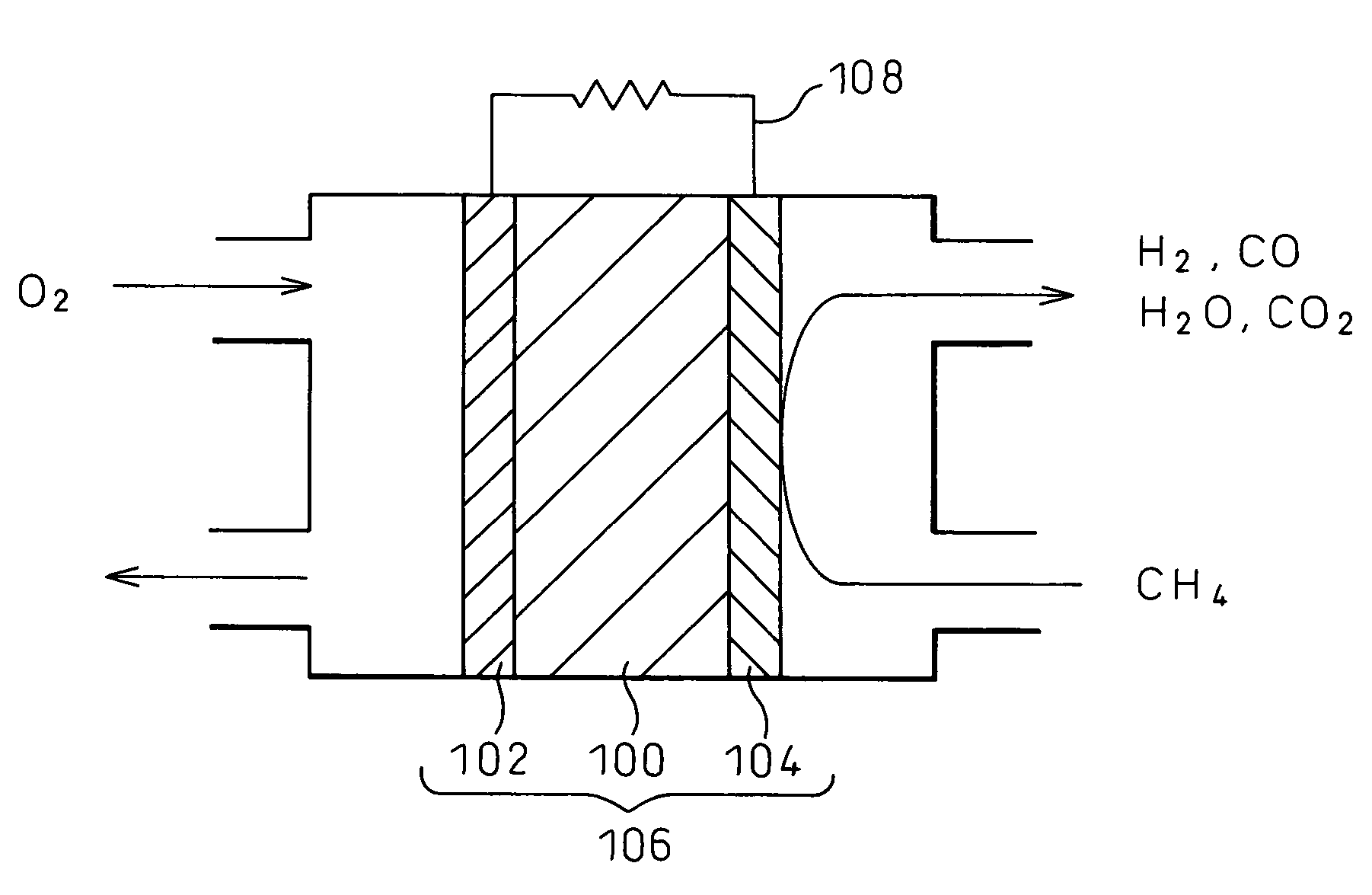
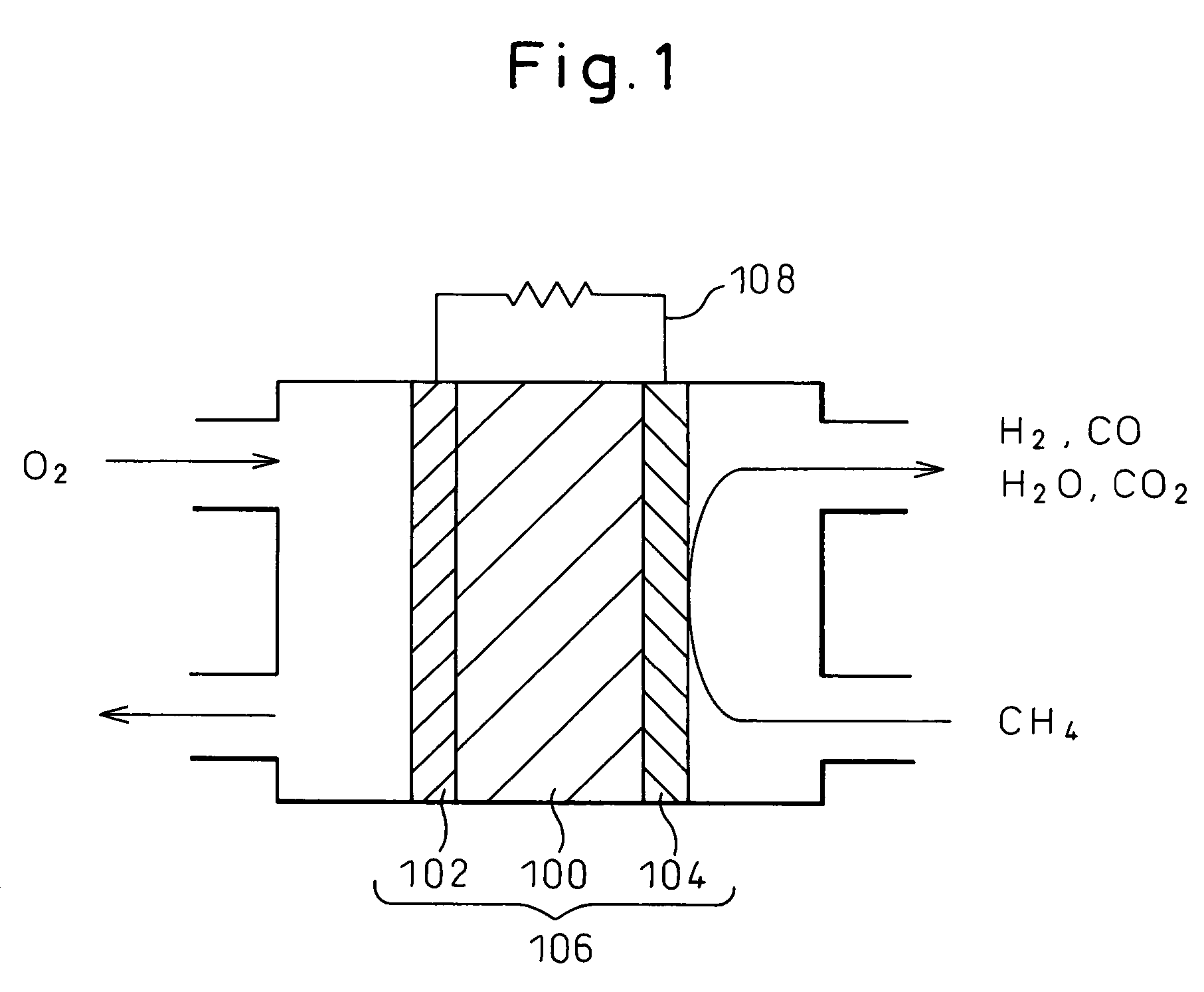
[0079]The fuel cell batteries fabricated in the foregoing example 1 were used as samples, and oxygen was supplied to the air electrode at a flow rate of 2×10⁻⁵ m3 / min, while dry methane (CH4) diluted with helium in a volume ratio of 1:9 was supplied as a fuel gas to the fuel electrode at a flow rate of 2×10⁻⁵ m3 / min. Power generation experiments were conducted at about 600 to 700° C. for the following items.

[0080][Comparison of Discharge Performance for Methane]

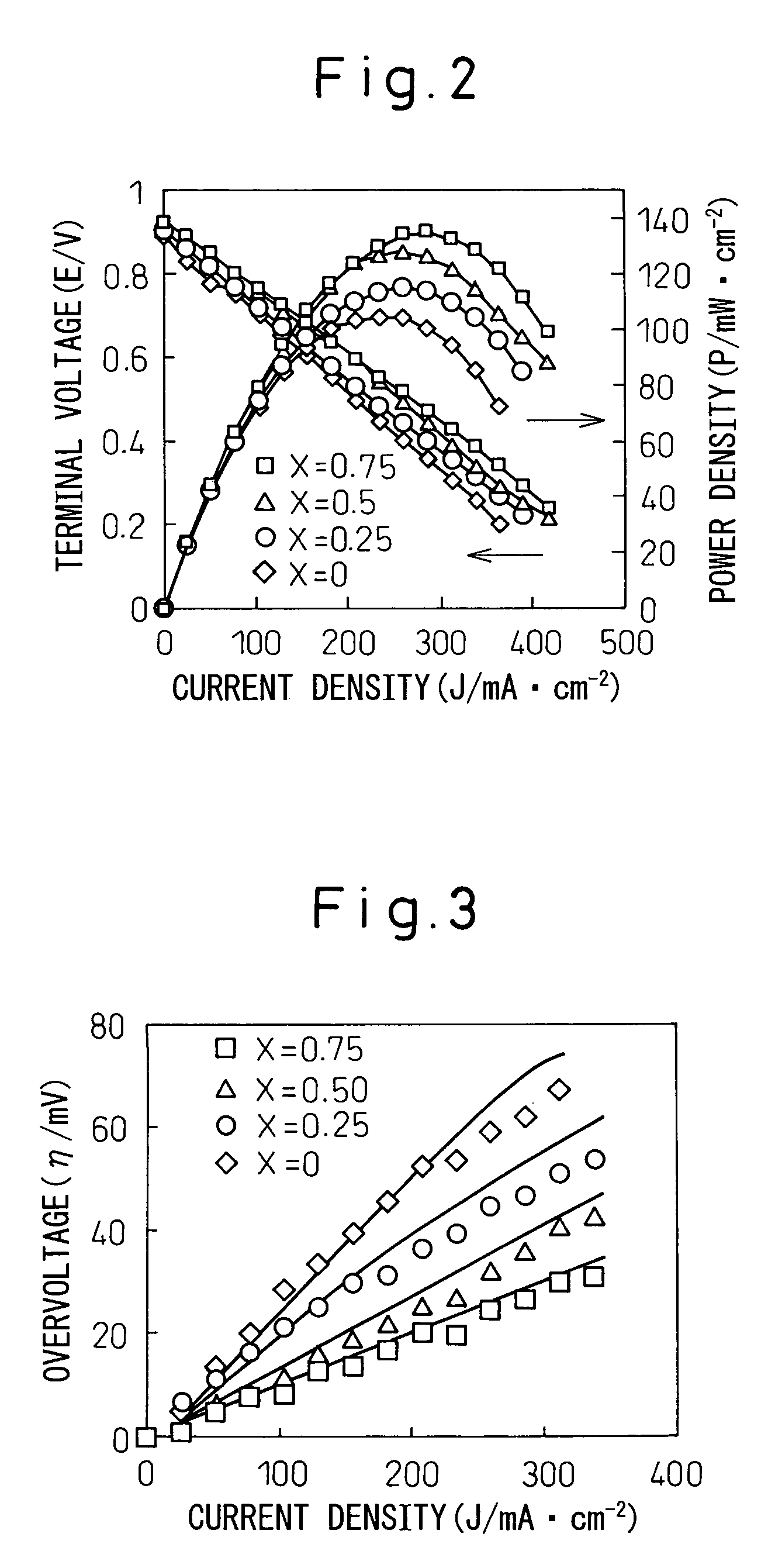
[0081]When open circuit voltage (terminal voltage) and output density (power density) were measured on each fuel cell sample while increasing the current density, measurement results plotted in FIG. 2 were obtained. As can be seen from the current density-voltage curves plotted in FIG. 2, when Ni1-xCox-SDC was used for the fuel electrode, the terminal voltage was 0.85 V or higher on any sample, and the power density increased with increasing amount of Co (x), the power density being the highest in the case of the fuel electro...

example 3

[0100]In this example, power generation experiments were conducted by repeating the method described in the foregoing example 2, with the difference that (1) hydrogen humidified by adding 3% by volume of vapor or (2) carbon monoxide (CO) was used as the fuel, instead of methane. The supply flow rate of hydrogen or carbon monoxide was set to 2×10⁻⁵ m3 / min., i.e., the same flow rate as that employed for methane. For all evaluation items, satisfactory evaluation results were obtained, as in the case of methane. Some of the experimental results are shown below.

[0101][Comparison of Discharge Performance for Hydrogen]

[0102]When the terminal voltage and the power density were measured on each fuel cell sample while increasing the current density, measurement results plotted in FIG. 9 were obtained. As can be seen from the current density-voltage curves plotted in FIG. 9, when Ni1-xCox-SDC was used for the fuel electrode, the terminal voltage was 0.85 V or higher on any sample, and the powe...


PUM

PropertyMeasurementUnit
specific surface areaaaaaaaaaaa
particle sizeaaaaaaaaaa

Abstract

A fuel cell electrode material comprising a cermet which comprises metal particles consisting of cobalt and nickel and electrolyte particles consisting of solid oxides, wherein the metal particles comprise 20 to 90 mol % cobalt and the residue of nickel in terms of CoO and NiO, respectively, and a solid oxide fuel cell battery comprising a fuel cell which comprises a solid electrolyte base, a fuel electrode formed on a fuel compartment side of the base, and an air electrode formed on an air compartment side of the base, wherein the fuel electrode is formed from the electrode material of the present invention.

Description

BACKGROUND OF THE INVENTION[0001]1. Field of the Invention[0002]The present invention relates to an electrode material that can be advantageously used as a fuel electrode in a fuel cell, and a fuel cell battery using a fuel electrode formed from such an electrode material. The fuel cell battery of the present invention not only can achieve higher fuel electrode performance than a conventional fuel cell battery using a nickel cermet as a fuel electrode, but also can effectively generate electricity without pre-reforming or humidifying a fuel, when methane and other gases are used as the fuel.[0003]2. Description of the Related Art[0004]Heretofore, fuel cells have been developed and commercially implemented as low-pollution power generating means to replace traditional power generating means such as thermal power generation, or as electric energy sources for electric vehicles that replace traditional engine-driven vehicles using gasoline or the like as a fuel. Especially, in recent ye...

Claims


Application Information

Patent Timeline
Patent Type & Authority Patents(United States)
IPC IPC(8): H01M4/00
CPCH01M4/8621H01M4/9016H01M4/9066H01M8/04022H01M8/04089H01M8/2425Y02E60/50H01M8/2432
Inventor SATO, KAZUNORITOKUTAKE, YASUEHORIUCHI, MICHIO
Owner SHINKO ELECTRIC IND CO LTD
Learn More