Optical pickup apparatus, objective optical element and optical information recording reproducing apparatus

a pickup apparatus and optical information technology, applied in the field of optical pickup apparatus, objective optical element and optical information recording reproducing apparatus, can solve the problems of increasing cost, plurality of optical, and reducing the accuracy of tracking operation, so as to reduce the cost, maintain the effect of tracking operation accuracy, and simplify the structur

Inactive Publication Date: 2010-02-02
KONICA MINOLTA OPTO
View PDF7 Cites 9 Cited by
  • Summary
  • Abstract
  • Description
  • Claims
  • Application Information

AI Technical Summary

Benefits of technology

[0009]The present invention is provided, with considering the above problems, to achieve at least one of the following objects. The present invention provides an optical pickup apparatus, an objective optical element, and an optical information recording reproducing apparatus which can properly conducts recording and / or reproducing information for three kinds of optical disks having different recording densities such as a high density optical disk, DVD and CD, even when using as the objective optical element, and which is capable of simplifying the structure and reducing the cost. In addition, the present invention provides an optical pickup apparatus, an objective optical element, and an optical information recording reproducing apparatus which can maintain accuracy of the tracking operation for all three different optical disks, even when using an infinite optical system. The present invention provides an optical pickup apparatus, an objective optical element, and an optical information recording reproducing apparatus which can provide excellent temperature characteristics and can properly conducts recording and / or reproducing information for the three kinds of disks, even when using a plastic lens for the objective optical element. The present invention provides an optical pickup apparatus, an objective optical element, and an optical information recording reproducing apparatus which provides desired optical characteristics and which can be easily manufactured without using minute structures.
[0011]The above embodiment allows that one objective optical element to properly record and / or reproduce information for three different disks (for example, a high density optical disk using a blue-violet laser light source, DVD, and CD) with employing a simple and low-cost configuration. Further, the above embodiment allows to provide an optical pickup apparatus, an objective optical element, and an optical information recording reproducing apparatus which can maintain accuracy of the tracking operation for all three different optical disks, even when using an infinite optical system. The above embodiment further allows to provide an optical pickup apparatus, an objective optical element, and an optical information recording reproducing apparatus which properly record and / or reproduce information for three different disks with using a single objective optical element. The above embodiment further allow to provide an optical pickup apparatus, an objective optical element, and an optical information recording reproducing apparatus which provide excellent temperature characteristics and properly record and / or reproduce information for three different disks with using a single objective optical element, even when employing a plastic lens.

Problems solved by technology

On the other hand, it is sometimes considered that a product, such as an optical disk player / recorder, which is capable of only recording / reproducing information for the above high-density optical disk is worthless.
However, it requires a plurality of optical systems, which is disadvantageous for the size-reduction and which increases the cost.
However, the objective optical element for use in the optical pickup apparatus which compatibly conducts recording and / or reproducing information for three different optical disks, which is written in EP-A 1304689, has a probability that the light amount used for recording and / or reproducing information is insufficient, depending on the design specification of the optical pickup apparatus, or has a problem that the unnecessary light affects a sensor for tracking operation when the tracking operation for CD is conducted, and the accurate tracking operation is hardly conducted, which is a problem.
Particularly, when using an infinite optical system for all three different kinds of optical disks, in other words, a collimated light flux enters into an objective optical element, the above problems become remarkable.

Method used


Image

  • Optical pickup apparatus, objective optical element and optical information recording reproducing apparatus
  • Optical pickup apparatus, objective optical element and optical information recording reproducing apparatus
  • Optical pickup apparatus, objective optical element and optical information recording reproducing apparatus

Examples


example

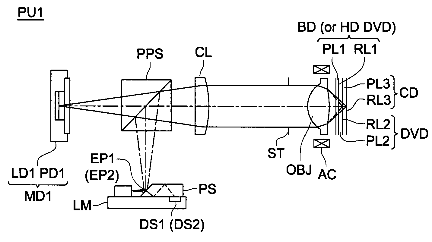
[0165]Referring to the drawings, the embodiment of the present invention will be described below. FIG. 3 is a view schematically showing optical pickup apparatus PU1 of the present embodiment capable of recording and / or reproducing information adequately for BD, DVD and CD which are different optical disks. The optical pickup apparatus PU1 can be mounted in the optical information recording and reproducing apparatus. Herein, the first optical disk is BD, the second optical disk is DVD, and the third optical disk is CD. Hereupon, the present invention is not limited to the present embodiment.

[0166]The optical pickup apparatus PU1 comprises objective optical element OBJ; aperture ST; collimator lens CL; polarizing dichroic prism PPS; first semiconductor laser LD1 (the first light source) which emits a laser light flux with a wavelength of 405 nm (the firs light flux) when recording / reproducing information for BD; and first light receiving element PD1 which receives the reflection ligh...

examples 1-3

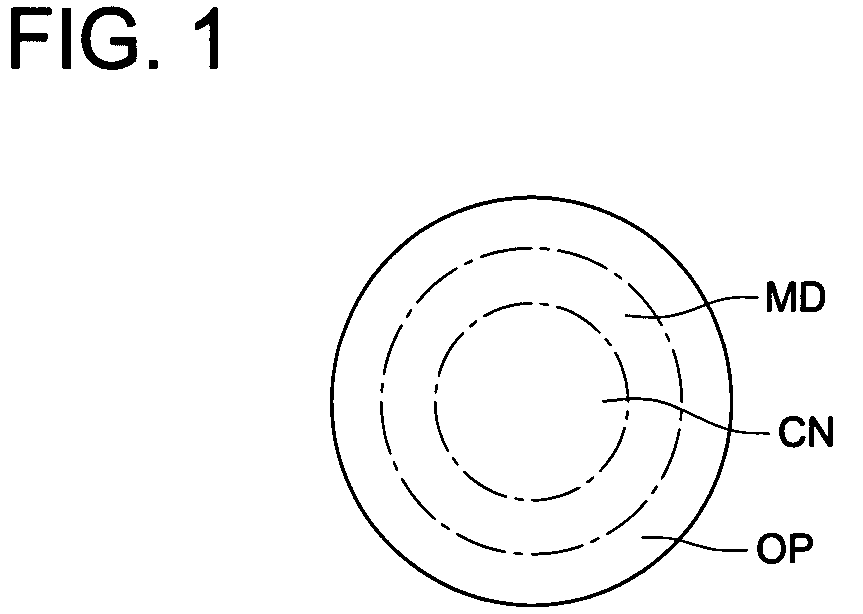
[0176]Next, examples which can be used for the above described embodiment will be described. In the following examples 1-3, the objective optical element is a single glass lens. The objective optical element comprises an optical surface including central area CN, the peripheral area MD, and the most peripheral area OT. The first optical path difference providing structure is formed on the entire surface of central area CN on the optical surface. The second optical path difference providing structure is formed on the entire surface of the peripheral area MD on the optical surface. The most peripheral area OT on the optical surface is the refractive surface in the aspheric shape.

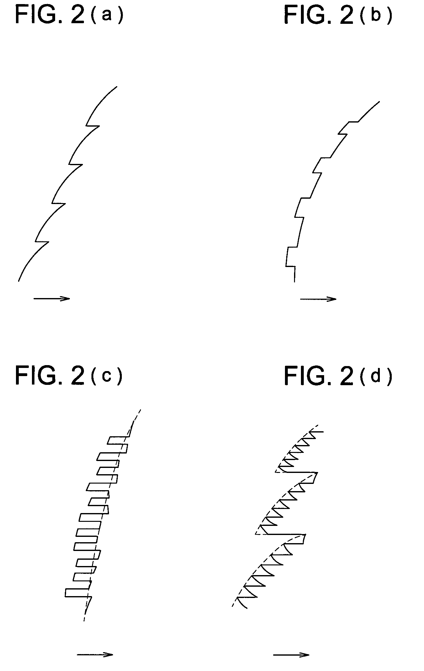
[0177]Further, in Examples 1-3, the first optical path difference providing structure is the structure formed by overlapping the first basic structure and the second basic structure and having a shape in which a serrated diffractive structure and a binary structure are overlapped. The sectional shape is likely...

example 1

[0187]The lens data of Example 1 will be shown in Tables 1-1 to 1-3. Further, FIGS. 5(a), 5(b), and 5(c) show the vertical spherical aberration diagrams of Example 1. The numeral 1.0 of the vertical axis of the vertical spherical aberration diagrams expresses NA 0.85, or a diameter of 3.74 mm in BD; expresses a value slightly larger than NA 0.60, or a diameter of 2.68 mm in DVD; and expresses a value slightly larger than NA 0.45, or a value slightly larger than a diameter of 2.18 mm in CD. Hereupon, L is 0.28 mm in Example 1. Accordingly, it provides L / F=0.28 / 2.42=0.116.

[0188]

TABLE 1-1Lens DataSingle diffractive lensFocal length of the objective lensf1 = 2.20 mmf2 = 2.28 mmf3 = 2.42 mmNumerical apertureNA1: 0.85NA2: 0.60NA3: 0.45Magnificationm1: 0m2: 0m3: 0The i-thsurfaceridi (405 nm)ni (405 nm)di (658 nm)ni (658 nm)di (785 nm)ni (785 nm)0∞∞∞1 (Stop0.00.00.0diameter)(φ3.74 mm)(φ2.68 mm)(φ2.18 mm)21.57952.4301.6052.4301.5862.4301.5822-11.57992-21.58042-31.58102-41.57932-51.58162-61.5...


PUM

PropertyMeasurementUnit
wavelengthaaaaaaaaaa
diameteraaaaaaaaaa
thicknessaaaaaaaaaa

Abstract

An optical pickup apparatus according to the present invention includes: a first light source for emitting a first light flux; a second light source for emitting a second light flux; a third light source for emitting a third light flux; and an objective optical element. The objective optical element has an optical surface including at least two areas provided with optical path difference providing structures. The objective optical element converges the first to third light fluxes each passing through the predetermined areas on the objective optical element onto respective information recording surfaces of the first to third optical disks. One of the optical path difference providing structures includes a first basic structure and a second basic structure which are predetermined optical path difference providing structures and overlap with each other.

Description

[0001]This application is based on Japanese Patent Application Nos. 2006-060968 filed on Mar. 7, 2006, 2006-070701 filed on Mar. 15, 2006, 2006-123471 filed on Apr. 27, 2006, 2006-166148 filed on Jun. 15, 2006, in Japanese Patent Office, the entire content of which is hereby incorporated by reference.BACKGROUND OF THE INVENTION[0002]The present invention relates to an optical pickup apparatus, objective optical element and optical information recording reproducing apparatus by which information can be recorded and / or reproduced information compatibly for different kinds of optical disks.[0003]In recent years, tendency of a shorter wavelength of laser beam as a light source which has been used to record and / or reproduce information for optical disks, has become a main stream. For example, a laser light source having 400-420 nm wavelength, such as a blue-violet semiconductor laser; and a blue-SHG laser which converts wavelength of an infrared semiconductor laser utilizing a second har...

Claims


Application Information

Patent Timeline
Patent Type & Authority Patents(United States)
IPC IPC(8): G11B7/00
CPCG02B27/42G02B27/4238G02B27/4283G11B7/1275G11B7/1353G11B7/1374G11B7/13922G11B7/123G02B3/08G11B2007/0006G02B5/18G02B13/00
Inventor NAKAMURA, KENTAROUOTA, KOHEIMORI, NOBUYOSHINOMURA, EIJI
Owner KONICA MINOLTA OPTO
Why Eureka
Try Eureka