Burner and method for induction of flue gas

a flue gas and burner technology, applied in the field of burners, can solve the problems of limiting the amount of nosub>x/sub>reduction achieved, and the temperature of the recirculated flue gas is still extremely high when it enters the combustion zone, so as to reduce the amount of nox emissions

Active Publication Date: 2010-03-02
ZEECO
View PDF14 Cites 102 Cited by
  • Summary
  • Abstract
  • Description
  • Claims
  • Application Information

AI Technical Summary

Benefits of technology

[0015]In another aspect, there is provided a method of reducing NOx emissions from a burner in a heating system having a flue gas therein, the burner including a burner wall having a forward end and an interior passageway having an outlet at the forward end, and the burner including a combustion zone wherein a combustion fuel is burned, the combustion zone beginning substantially at the forward end. The method comprises the step of disc

Problems solved by technology

However, when the fuel is burned under less than ideal conditions, such as in a high temperature environment, nitrogen present in the combustion air reacts with oxygen to produce nitrogen oxides (NOx).
However, when the flue gas is recirculated from the interior of the fired heater without significant

Method used


Image

  • Burner and method for induction of flue gas
  • Burner and method for induction of flue gas
  • Burner and method for induction of flue gas

Examples


embodiment 2

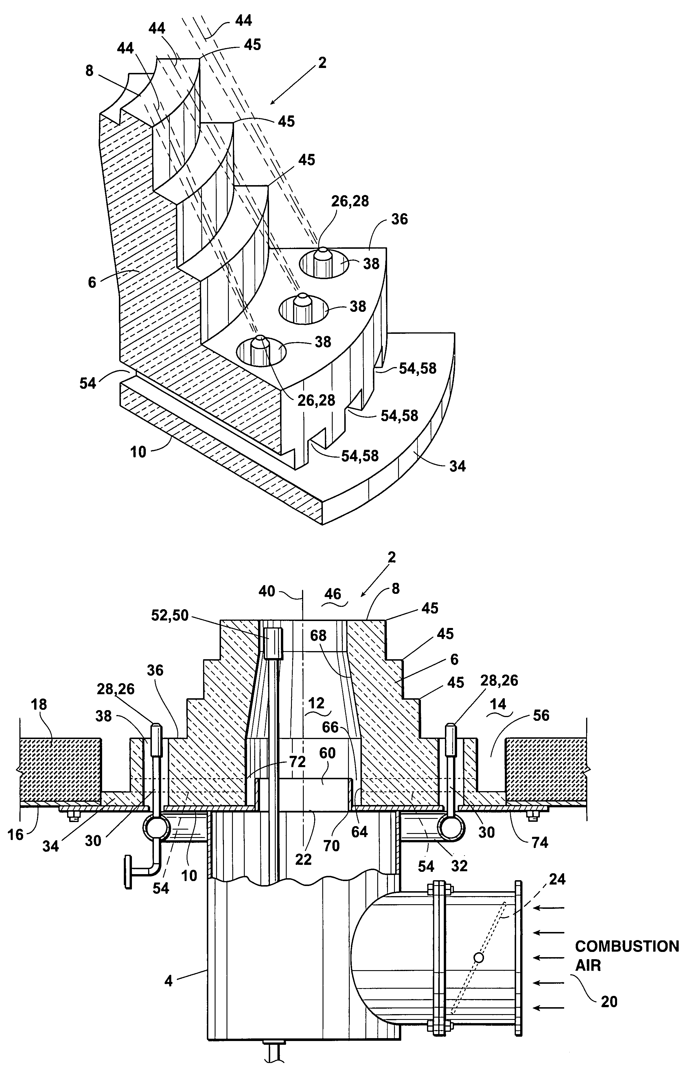
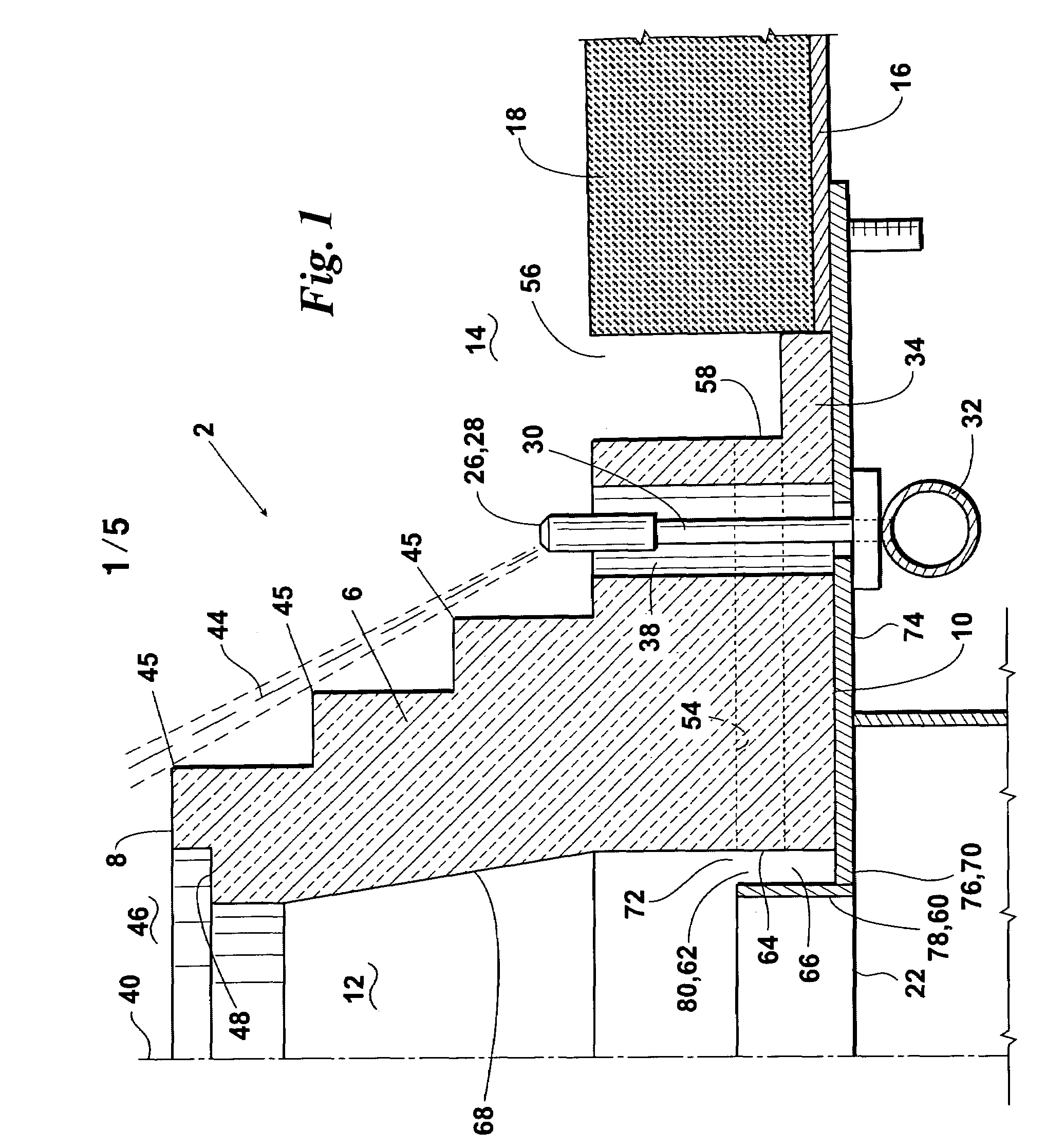
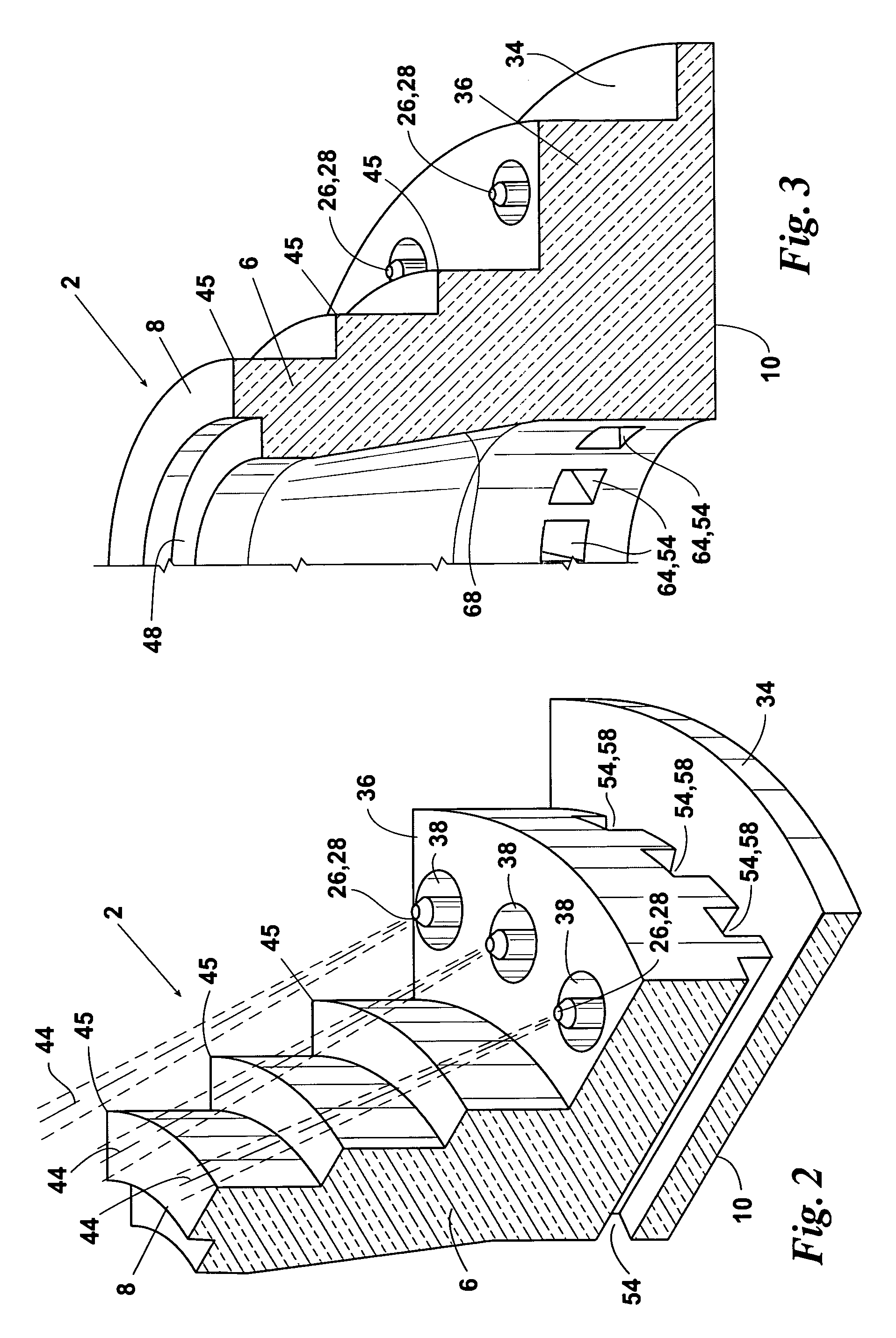
[0025]The present invention can be used in burners designed for combusting gas fuel, liquid fuel, or a combination thereof. In embodiment 2 of the inventive burner, the burner wall 6 is preferably surrounded by a series of ejection tips, nozzles, or other fuel gas ejectors 26. Each ejector 26 is depicted as comprising a fuel ejection tip 28 secured over the distal end of a fuel pipe 30. Each fuel pipe 30 is in communication with a fuel supply manifold 32 and preferably extends through an outer portion of the base 10 of the burner wall 6. As another alternative, the fuel ejectors could be positioned completely outside of the base end 10 of burner wall 6. Each of the ejectors 26 preferably extends through a channel 38 which is formed through a lower outer ledge portion 36 of the burner wall 6 and which runs parallel to the longitudinal center line 40 of the burner wall 6.

[0026]Each of the fuel gas ejectors 26 can have any desired number of ejection ports 42 provided therein. Such port...

embodiment 100

[0044]An alternative embodiment 100 of the inventive low NOx burner is illustrated in FIG. 6. As with the inventive burner 2, the inventive burner 100 is preferably a single stage burner wherein the burner wall 106 includes: a central air passageway 112 extending therethrough; a forward end opening 108 which is in communication with the interior 114 of a furnace or other heating system enclosure which contains a flue gas; and one or more, preferably a plurality of, flue gas induction channels 154 which preferably extend laterally through the burner wall 106 near the base end thereof.

[0045]Also similar to inventive burner 2, the inventive burner 100 preferably comprises: an inlet air duct 102 having a damper or other regulating device 124 therein; one or more, preferably a plurality of, outer fuel gas ejectors 126 extending from a fuel supply manifold 132; and an outer gap 156 surrounding the burner wall 106. The inlet ends 158 of the induction channels 154 are located in the outer g...


PUM


Abstract

A low NOx burner and method wherein (a) combustion air flows through the interior of the burner in a manner effective for drawing an amount of inert flue gas diluent from the fired heating system into the combustion air stream, preferably via one or more induction channels provided through the burner wall, and/or (b) air or an inert gas is discharged into the induction channel(s) in a manner effective for delivering flue gas into the combustion air stream.

Description

FIELD OF THE INVENTION[0001]The present invention relates to burners and methods which utilize flue gas recirculation for reducing NOx emissions from process heaters, boilers, and other fired heating systems.BACKGROUND OF THE INVENTION[0002]Many industrial applications require large scale generation of heat from burners for process heaters, boilers, or other fired heating systems. If the burner fuel is thoroughly mixed with air and combustion occurs under ideal conditions, the resulting combustion products are primarily carbon dioxide and water vapor. However, when the fuel is burned under less than ideal conditions, such as in a high temperature environment, nitrogen present in the combustion air reacts with oxygen to produce nitrogen oxides (NOx). It is well known that, other conditions being equal, NOx production increases as the temperature of the combustion process increases. NOx emissions are generally considered to contribute to ozone depletion and other environmental concern...

Claims


Application Information

Patent Timeline
IPC IPC(8): F23M3/00F23M3/12
CPCF23C9/00F23D14/22F23M5/025F23C2202/30
Inventor ZINK, DARTON J.ISAACS, REX K.MCDONALD, JOHNKIRK, TIMLITTLE, CODY L.
Owner ZEECO
Why Eureka
Try Eureka