Radio receiver and radio signal receiving method

a radio receiver and radio signal technology, applied in the field of wireless communication techniques, can solve the problems of inability to accurately measure the difference between receiving timing and streaming transmission, inability to use gps, and inability to produce an acceptable delay in real-time communication and streaming transmission

Inactive Publication Date: 2010-03-02
NTT DOCOMO INC
View PDF8 Cites 30 Cited by
  • Summary
  • Abstract
  • Description
  • Claims
  • Application Information

AI Technical Summary

Benefits of technology

[0009]To overcome at least one of the above-described problems, embodiments of the present invention provide a radio receiver and a signal receiving method of an orthogonal frequency division multiplexing (OFDM) scheme that can accurately measure the receiving timing difference between a desired signal and an undesired signal even under the multipath environment.
[0016]With this structure, a timing difference between a desired signal reception and an undesired signal reception can be determined accurately even under the multipath environment.

Problems solved by technology

Since with CSMA / CA a user cannot start transmission when another user is communicating, unacceptable delay may be produced in real-time communications and streaming transmission.
In addition, as the number of users increases, communication may be restricted for a long period of time depending on the user environment.
However, using GPS is disadvantageous indoors or when not in line-of-sight, and using a synchronizing signal requires additional expense.
With the latter method, synchronization cannot be assured if the transceivers are out of the service area.
With these methods, however, counterpart transceivers (or mobile stations) with which a certain transceiver is going to communicate are restricted by the base-station configurations, and accordingly, they cannot be applied as they are to an adhoc network.
In addition, it is difficult in reality in a rapidly changing environment to select and fix a base station most suitable for the reference base station in advance from among many base stations.
An undesirable signal component is also contained in the measured channel impulse response due to imperfection in orthogonality between pilot signals.
These undesirable facts prevent accurate measurement of the receiving timing of each path.

Method used


Image

  • Radio receiver and radio signal receiving method
  • Radio receiver and radio signal receiving method
  • Radio receiver and radio signal receiving method

Examples


embodiment 1

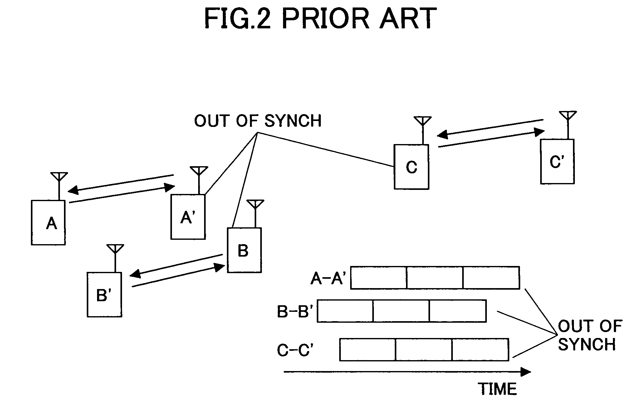
[0060]FIG. 6 is a schematic diagram illustrating mobile terminal pairs A-A′ and B-B′ communicating in sync with each other in the same frequency band. The mobile terminals may be another type of radio communication apparatus. The mobile terminals A and B are operating under the resource allocation for symbols shown in FIG. 7. Pilot symbols and data symbols are time-multiplexed, while the pilot symbols of mobile terminal A and the pilot symbols of mobile terminal B are multiplexed alternately along the frequency axis. In the following, explanation is made of how mobile terminal A′ currently communicating with mobile terminal A detects a timing difference between reception of a signal from mobile terminal (counterpart device) A and reception of a signal from mobile terminal (non-counterpart or non-connected device) B.

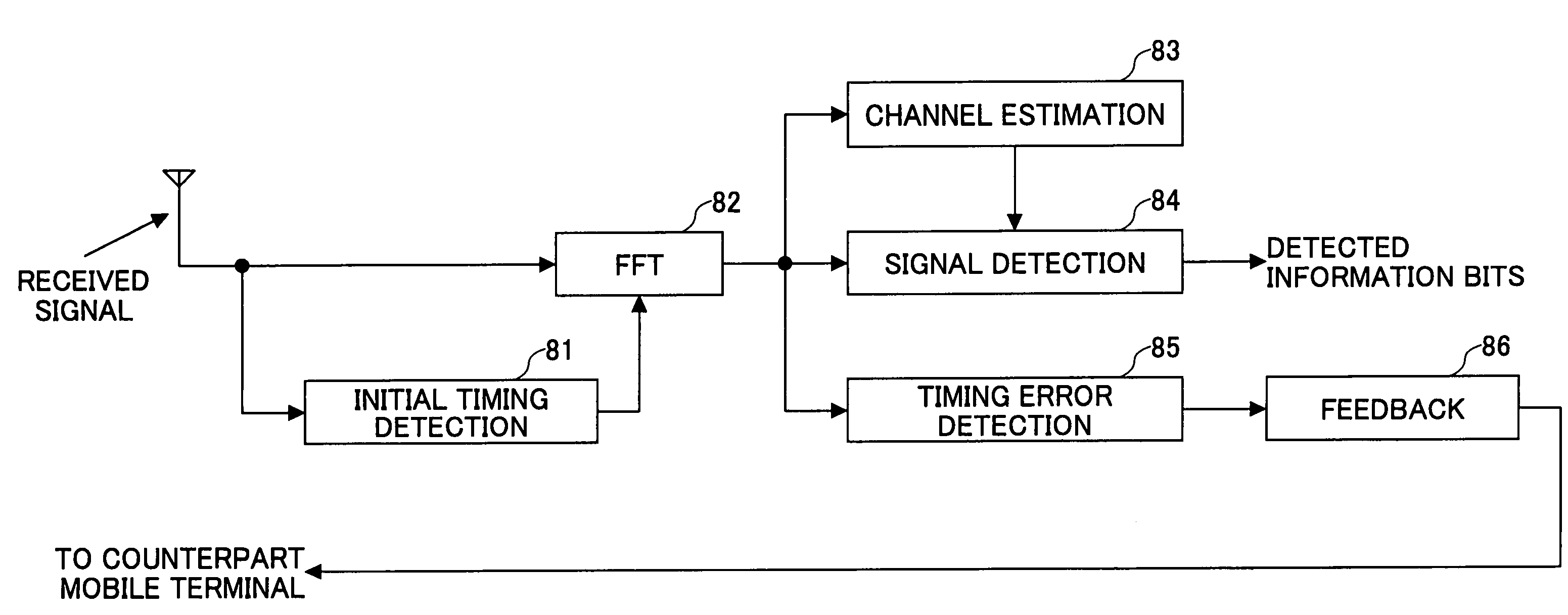
[0061]FIG. 8 is a block diagram of a receiver of the mobile terminal A′ employing an OFDM signal transmission / receiving scheme. The receiver includes an initial timing de...

embodiment 2

[0077]FIG. 11 is a schematic diagram illustrating resource allocation for symbols when the entire range of a frequency band is shared among three mobile terminals, unlike the previous embodiment shown in FIG. 7 in which two mobile terminals share the entirety of a frequency band. By determining an impulse response for each of the three mobile terminals, a receiving timing difference can be determined. In this case, however, IFFT operations at the timing error detection unit 85 are performed three times. In general, to determine impulse responses for N mobile terminals, N times IFFT operations have to be carried out.

[0078]FIG. 12 is a block diagram of the timing error detection unit 85 suitable for the arrangement shown in FIG. 11. The components shown in FIG. 9 are denoted by the same symbols. Demultiplexer 121 detects each of the pilot symbols appropriately, just like demultiplexer 91. In this example, each of the three types of pilot symbols placed at certain intervals along the f...

embodiment 3

[0081]In the third embodiment, a frequency band is divided into multiple frequency blocks (or subcarrier blocks), which arrangement is different from the first and second embodiments in which each user uses the entire range of the frequency band. In general, each of the frequency blocks includes one or more subcarriers. Each user carries out radio communications using one or more frequency blocks. Under this arrangement, the mobile terminals still have to be in sync with each other; otherwise, the desired signal and undesired signals cannot be appropriately detected and the signal quality is degraded due to interference between the frequency blocks used by the desired signal and the undesired signals. The signal quality can be measured based on the bit error rate, throughput, SIR, etc.

[0082]FIG. 13 is a schematic diagram illustrating an example of resource allocation for pilot symbols under the subcarrier block configuration. In this example, subcarrier block 1 is used by mobile ter...


PUM


Abstract

An OFDM receiver includes a timing error detection unit that determines error information based on a difference between receiving timing of a desired signal from a counterpart transmitter and receiving timing of an undesired signal from a non-counterpart transmitter. The timing error detection unit includes a pilot signal detection unit configured to detect a pilot signal of the desired signal and a pilot signal of the undesired signal from an FFT-processed received signal; a first converting unit configured to convert a frequency-domain channel estimate derived from the pilot signal of the desired signal to a first time-domain channel impulse response; a second converting unit configured to convert a frequency-domain channel estimate derived from the pilot signal of the undesired signal to a second time-domain channel impulse response; and an error information determination unit configured to determine the error information based on the first and second channel impulse responses.

Description

FIELD OF THE INVENTION[0001]The present invention generally relates to a wireless communication technique, and more particularly to an OFDM radio receiver and radio signal receiving method used in a mobile communication system allowing multiple mobile devices to perform radio communications in sync with each other using the same frequency band.BACKGROUND OF THE INVENTION[0002]Carrier sense multiple access with collision avoidance (CSMA / CA) is a known network control protocol, in which a carrier sensing scheme is used to allow multiple radio transceivers to share the same frequency band for radio communications under collision avoidance control, and it may be applied to wireless LANs (local area networks). With CSMA / CA, a transceiver performs carrier sensing prior to data transmission in order to determine whether there is another user carrying out radio communication. The transceiver can start transmitting data packets only if no users are sensed. Presence or absence of other users ...

Claims


Application Information

Patent Timeline
Patent Type & Authority Patents(United States)
IPC IPC(8): H04J11/00H04W56/00
CPCH04L25/0206H04L25/0212H04L27/2662H04W56/0065H04L27/2675H04L27/2676H04L27/2695H04L25/0204
Inventor FUJI, HIROMASAYOSHINO, HITOSHISUGIYAMA, TAKATOSHI
Owner NTT DOCOMO INC
Why Eureka
Try Eureka