Distance measuring system
a distance measurement and distance measurement technology, applied in distance measurement, instruments, surveying and navigation, etc., can solve the problems of complex structure of optical modulators (formed by ln substrates) and optical wavelength filters in use of distance measurement techniques, and achieve the effect of simple structure and less expensiv
- Summary
- Abstract
- Description
- Claims
- Application Information
AI Technical Summary
Benefits of technology
Problems solved by technology
Method used
Image
Examples
embodiment
First Embodiment
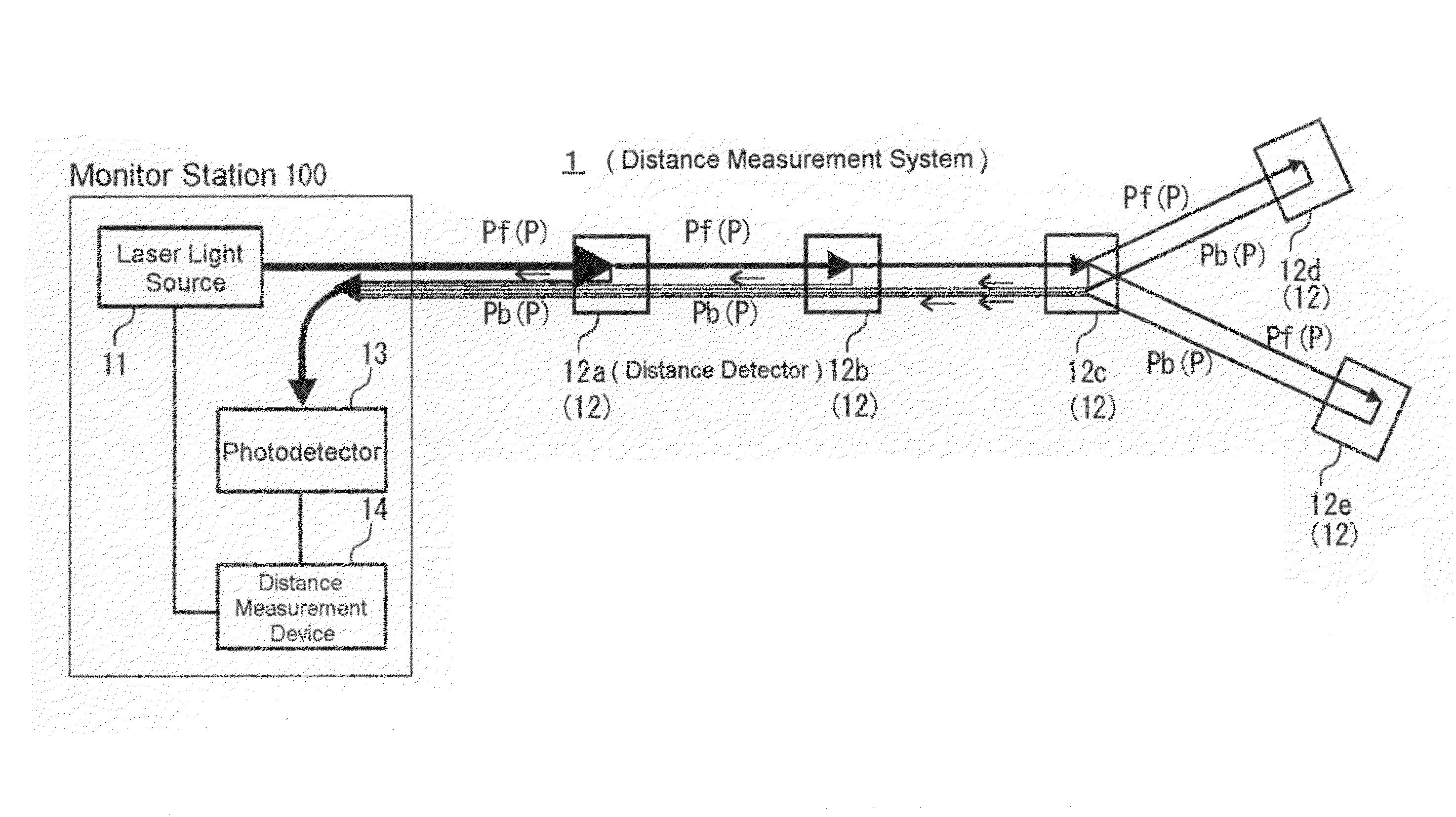
[0082]FIG. 6 is a block diagram showing the first embodiment of the present invention. The distance measurement system 2 shown in FIG. 6 comprises a laser light source 21, a distance detector 22, a photodetector 23 and a distance measurement apparatus 24.
[0083]In this embodiment, a photodetector 235 receives the laser light B3 from a second optical amplifier 234 and induces Two-Photon Absorption (TPA).
[0084]The laser light source 21 includes a semiconductor laser 211 and a fiber collimator FC1, and the fiber collimator FC1 is the starting point of the path P in this embodiment. In this embodiment, the light from the semiconductor laser 211 (the first laser light source) is directly modulated by a VCO (Voltage Controlled Oscillator, controlled by a controller 242).
[0085]In FIG. 6, three distance detectors (each includes an optical component) on the path P are shown with the reference numerals 221A, 221B and 221C.
[0086]Actually, the length of the path P between the sta...
second embodiment
[0098]FIG. 7 shows the distance measurement system 2 having an optical axis adjuster.
[0099]As shown in FIG. 8(C), an optical axis adjuster 4 comprises a controller 223 and a transmitter / receiver 224 arranged in the distance detectors 22A, 22B and 22C.
[0100]The controller 223 comprises a control circuit 225 and an adjusting mechanism 222 for adjusting position and direction of the distance detectors 22A, 22B and 22c. The optical axis adjuster 4 and the controller 223 in FIG. 7 are shown without reference numerals.
[0101]As shown in FIG. 8(C), the controller 242 in the distance measurement apparatus 24 located in the monitor station 100 provides the detection result (light intensity) obtained by the frequency detector 241 to the transmitter / receiver 243, and the transmitter / receiver 243 provides it to the transmitter / receiver 244 in the distance detectors 22A, 22B and 22C.
[0102]The control circuit 225 controls the position and direction adjusting mechanism 222 by comparing a detected r...
third embodiment
[0110]FIG. 10 is a block diagram showing the third embodiment of the present invention comprising a single beam system. The distance measurement system 5 shown in FIG. 10 comprises a laser light source 51, a distance detector 52, a photodetector 53 and a distance measuring apparatus 54.
[0111]The laser light source 51 includes a semiconductor laser 211. In this embodiment, a fiber collimator FC is mounted at the subsequent stage of the circulator C. The fiber collimator FC functions as the starting point of the path P as well as the inlet for the light coming back through the path P.
[0112]The distance detectors 52A, 52B, 52C and 52D are positioned on the way of the path P starting at the position of the fiber collimator FC or the circulator C.
[0113]The distance detector 52A comprises a prism, on which a semitransparent mirror H is formed at the starting point side of the path P. The distance detector 52A reflects part of the light to the fiber collimator FC, and transmits the remaini...
PUM
 Abstract
Description
Claims
Application Information
 - R&D
- Intellectual Property
- Life Sciences
- Materials
- Tech Scout
- Unparalleled Data Quality
- Higher Quality Content
- 60% Fewer Hallucinations
Browse by: Latest US Patents, China's latest patents, Technical Efficacy Thesaurus, Application Domain, Technology Topic, Popular Technical Reports.
© 2025 PatSnap. All rights reserved.Legal|Privacy policy|Modern Slavery Act Transparency Statement|Sitemap|About US| Contact US: help@patsnap.com


