
Packet transmitter apparatus

a transmitter and package technology, applied in the field of package transmitter equipment, can solve the problems of heavy processing load in the receiver side, inability to transmit mpeg-ts signals through the network, and digital copyright protection, and achieve the effects of high importance, and secure compatibility of signals

Active Publication Date: 2010-03-16
PANASONIC CORP
View PDF12 Cites 20 Cited by
  • Summary
  • Abstract
  • Description
  • Claims
  • Application Information

AI Technical Summary

Benefits of technology

[0032]With the first invention, an encryption mode in transmission of the AV contents is determined according to a predetermined rule provided from outside. Further, since a rule for adding encryption information headers is determined, it is possible to secure compatibility of a signal maintaining confidentiality of the AV stream between packet transmitter and receiver apparatuses.
[0033]With the second invention, in the authentication unit in the first invention, an authentication execution mode is determined based on control information of outside input. For example, a URI specifying an access position of each contents can be provided as control information inputted from outside, and each authentication mode is determined according to the URI format. As an example, in the case where the URI is extended by a Query format, information indicating that authentication is needed and the information of a TCP port number for authentication according to the Query information can be provided at the same time. In this way, an authentication execution mode can be determined based on control information to be inputted from outside.
[0034]With the third invention of the present invention, in the encrypted data generation in the first invention, the AV stream's copy control information is complied with as prescribed transmitting conditions provided from outside, and an encryption mode and addition of encryption information headers are determined. In this way, an encryption mode of the AV stream such as an MPEG-TS signal is determined according to the copy control information, and encryption information headers are added. Subsequently, packets of the AV data are generated and transmitted. Therefore, the packets are transmitted succeeding the copy control mode which has been set by the copyright owner of the AV contents. In other words, since processing by a predetermined rule can be performed, it becomes possible to secure compatibility of a signal between packet transmitter and receiver apparatuses protecting the copyright of the AV contents.
[0035]With the fourth invention, the AV data and non-AV data in the first invention are inputted into data buffers respectively, and outputted to the packet header addition unit while output priority control of these two buffers is performed. For example, the AV data is outputted preferentially from the data buffer while the buffer of the non-AV data is being controlled in order not to overflow. In this way, it becomes possible to preferentially transmit data with high importance among the AV data and the non-AV data.
[0036]With the fifth invention, a timestamp is added to each data block which constitutes the AV data in the first invention, and integrated one or more data blocks with timestamps are mapped onto the payload part of an RTP packet or the payload part of an HTTP packet. For example, in the case of MPEG-TS AV data, a timestamp is added to each TS packet, and integrated TS packets with timestamps are mapped onto an RTP packet or an HTTP packet. For example, it is possible to use an MPEG system clock frequency as the clock of timestamps to be added to the respective TS packets. With the timestamps added to the TS packets, it becomes possible to remove transmission jitters added to a Program Clock Reference (PCR) when an MPEG-TS is transmitted through a network and enable a receiver side to restore the MPEG system clock.
[0037]With the sixth invention of the present invention, packets of AV data in the first invention are generated by means that the receiver side performs switching control of RTP and HTTP. For example, AV data packets are generated using RTP which provides small delays in the case where AV data output is outputted to the display of the receiver side. AV data packets are generated using HTTP which reduces the number of packet losses in the case where AV data output is stored in a storage medium. In this way, in the case where the receiver side outputs the AV contents to the display by performing switching control, it becomes possible to transmit AV contents at a low delay rate and to transmit AV contents which become high quality through compensation of a signal loss due to a packet loss.

Problems solved by technology

However, in the above conventional technique, there are the following problems.
However, it has a big problem that it cannot transmit the MPEG-TS signal through the networks such as the Ethernet (registered trademark) (IEEE 802.3), the wireless LAN (IEEE 802.11), and other networks which are available for transmission of IP packets, using the Internet Protocol (IP) which is the standard protocol of the Internet.
In other words, it has a big problem that it cannot transmit contents subjected to digital copyright protection such as ground / BS digital broadcasting and server broadcasting between the packet transmitter apparatus and the packet receiver apparatus which are logically connected through IP, while protecting the copyright of the contents.
Therefore, it has a problem that the processing load in a receiver side is heavy.
Further, it has a problem that it has difficulty in performing trick playback of contents stored in a hard disc or the like in a simple manner.
Further, it has a problem that it has difficulty in performing trick playback of contents which have different storage formats and are stored in a hard disc, an optical disc or the like using a common scheme in a simple manner.

Method used


Image

  • Packet transmitter apparatus
  • Packet transmitter apparatus
  • Packet transmitter apparatus

Examples


first embodiment

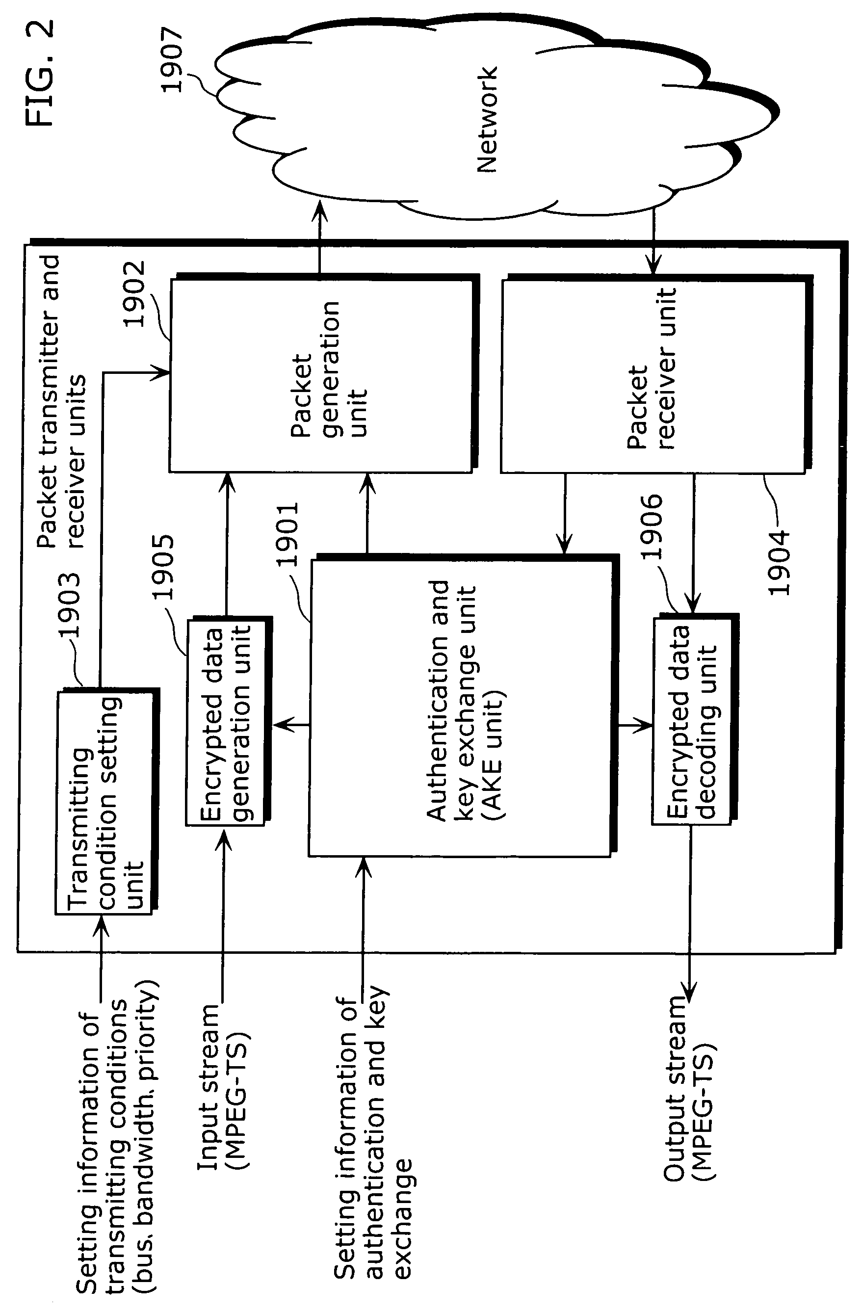
[0144]First, a first embodiment of the present invention will be described. FIG. 9 is a block diagram showing the configuration of a packet transmitter and receiver unit 401 in this embodiment. This packet transmitter and receiver unit 401 is a virtual function block which shows a packet transmitter unit provided with the packet transmitter apparatus 101 shown in FIG. 5 and a packet receiver unit provided in the router 102. Additionally, it may be a functional block showing a single packet transmitter and receiver unit which has a packet transmitting and receiving function (this is true of the packet transmitter and receiver unit(s) in all the following embodiments).

[0145]This packet transmitter and receiver unit 401 is an apparatus which performs packet transmitting and receiving by encryption using AKE. It includes an AKE unit 402, a packet generation unit 403, a transmitting condition setting management unit 404, a packet receiver unit 405, an encrypted data generation unit 406, ...

second embodiment

[0165]Next, a second embodiment of the present invention will be described. FIG. 11 is a block diagram showing the configuration of a packet transmitter and receiver unit 401a in this embodiment. In FIG. 11, it has the same configuration as the packet transmitter and receiver unit 401 shown in FIG. 9 except that it has an authentication mode determination unit 601. Hence, the new part will be described below.

[0166]In FIG. 11, as shown in this figure, a TCP port number for authentication is inputted in the transmitting condition setting management unit 404 as management control data such as the AKE setting information to the AKE unit 402. Here, the TCP port information for authentication is provided according to the URI specifying an access position of each contents or each broadcasting channel, or URI information extended by a Query. At this time, as to the URI, URI information is mapped onto the principal data part of the contents and authentication information of the contents are ...

third embodiment

[0170]Next, a third embodiment of the present invention will be described. FIG. 12 is a block diagram showing the configuration of a packet transmitter and receiver unit 401b in this embodiment. In FIG. 12, the packet transmitter and receiver unit 401a has the same configuration as the packet transmitter and receiver unit 401a in the second embodiment shown in FIG. 11 except that input source information (broadcast or stored) of AV data is inputted into the transmitting condition setting management unit 404. Hence, the new part will be described below.

[0171]From the transmitting condition setting management unit 404, necessary data among the input source information (broadcast or stored) of inputted AV data are extracted and outputted to the encrypted data generation unit 406. Subsequently, the encryption information header addition unit 412 inside the encrypted data generation unit 406 adds the necessary data transmitted from the transmitting condition setting management unit 404 a...


PUM


Abstract

To provide a packet transmitter apparatus which can transmit contents protected by a content protection technique such as DTCP or the like, using packets such as IP packets which have become widespread.The packet transmitter apparatus includes a transmitting condition setting management unit (404) which extracts at least one of charge information, playback control information and copy control information of AV data from the inputted non-AV data or AV data and generates, based on the extracted information, encryption mode information indicating an encryption mode which becomes a condition at the time of transmitting the AV data; an encrypted data generation unit (406) which generates encrypted data by encrypting, based on the transmitting condition, the inputted AV data and adding encryption information headers based on the encryption mode information to the encrypted AV data; and a packet generation unit (403) which generates packets by adding packet headers to the generated encrypted data. The transmitting condition is to be determined as a combination of input terminal information, data format information and attribute information.

Description

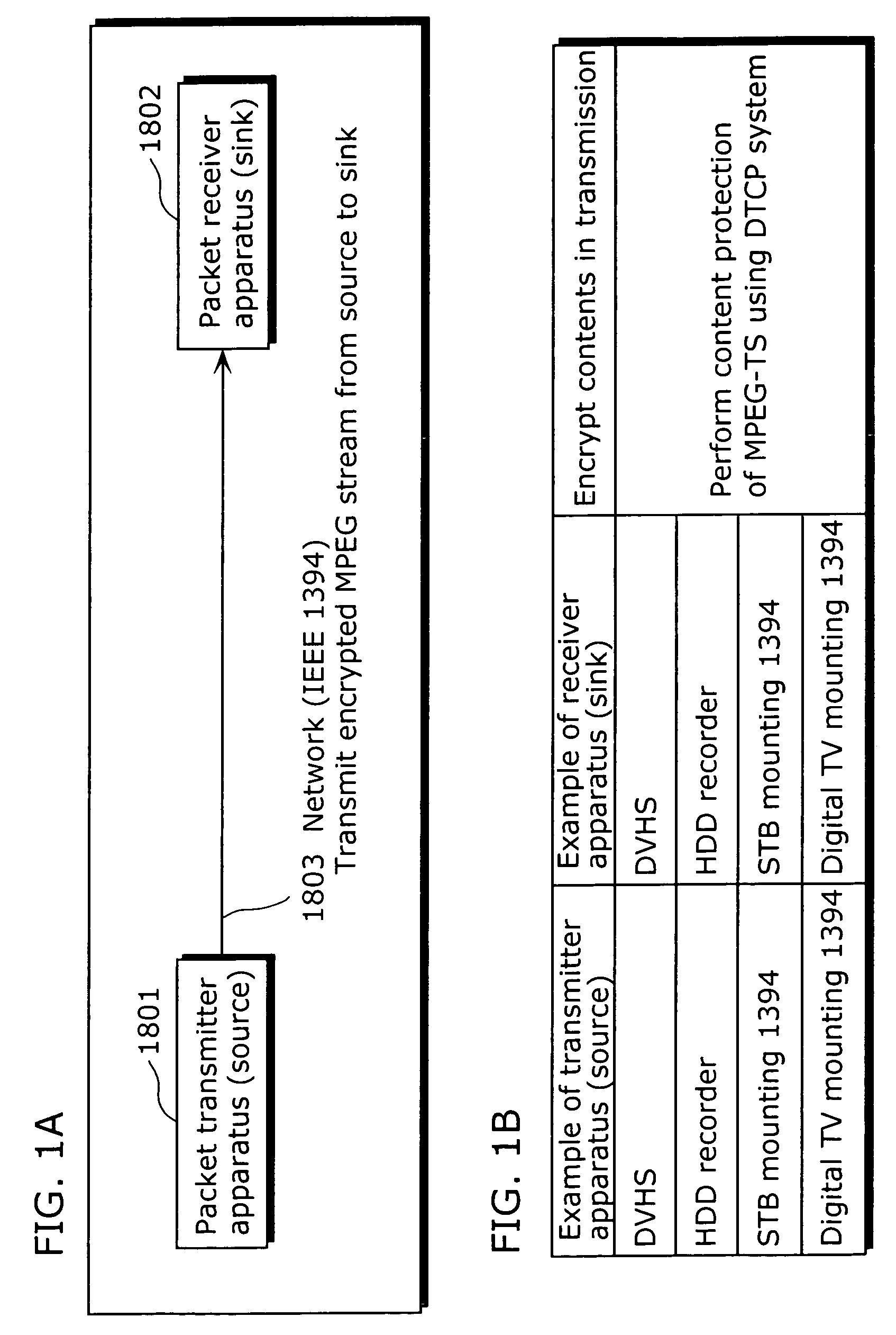
TECHNICAL FIELD[0001]The present invention relates to a packet transmitter apparatus which generates IP packets of an encrypted audio and video (AV) stream and transmits the packetized stream using an Ethernet (registered trademark, a wired LAN) such as IEEE 802.3 or a wireless LAN such as IEEE 802.11.BACKGROUND ART[0002]With recent development of communication techniques, various techniques for transmitting packets efficiently have been provided (for example, refer to Patent Reference 1). As one of these, a Moving Picture Experts Group Transport Stream (MPEG-TS) signal defined in the IEC 61883-4 has been conventionally transmitted by connecting a digital broadcasting tuner with a DVHS system video recorder in a room in a general home, using an IEEE 1394 method digital interface. Here, in the case where broadcast contents have been subjected to content protection such as Copy One Generation, the contents are encrypted and transmitted in order to protect the contents from unauthorize...

Claims


Application Information

Patent Timeline
Patent Type & Authority Patents(United States)
IPC IPC(8): G06F7/04G06F15/16G06F9/00H04N7/16G06F17/30G06F17/00G06F11/30H04N7/167H04K1/00G06F12/14H04L9/36H04L12/22H04L29/06H04N7/173H04N21/2389H04N21/266
CPCH04L63/0428
Inventor MORIOKA, YOSHIHIROAYAKI, YASUSHIUSUKI, NAOSHI
Owner PANASONIC CORP
Learn More