Transmitter apparatus and wireless communication apparatus

a technology of transmitter apparatus and wireless communication, which is applied in the direction of power management, phase-modulated carrier system, baseband system details, etc., can solve the problems of small power efficiency, insufficient transmission output level range of communication apparatus, and inability to achieve the necessary transmission output level range. achieve the effect of wide output control and high efficiency

Inactive Publication Date: 2010-03-23
PANASONIC CORP
View PDF18 Cites 33 Cited by
  • Summary
  • Abstract
  • Description
  • Claims
  • Application Information

AI Technical Summary

Problems solved by technology

The class A amplifier has small distortion, namely, is excellent in linearity, but provides small power efficiency because it consumes power accompanying a DC bias component at all times.
Thus, the necessary transmission output level range cannot sufficiently be secured in a communication apparatus requiring a wide output control variable width as in a recent mobile telephone standard (for example, about 43 dB+α in EGPRS of European mobile telephone standard).
Therefore, to prolong the conversion-possible time of a mobile telephone, suppressing the power consumption not only at the maximum transmission output time, but also at the low transmission output time is an important problem.

Method used


Image

  • Transmitter apparatus and wireless communication apparatus
  • Transmitter apparatus and wireless communication apparatus
  • Transmitter apparatus and wireless communication apparatus

Examples


first embodiment

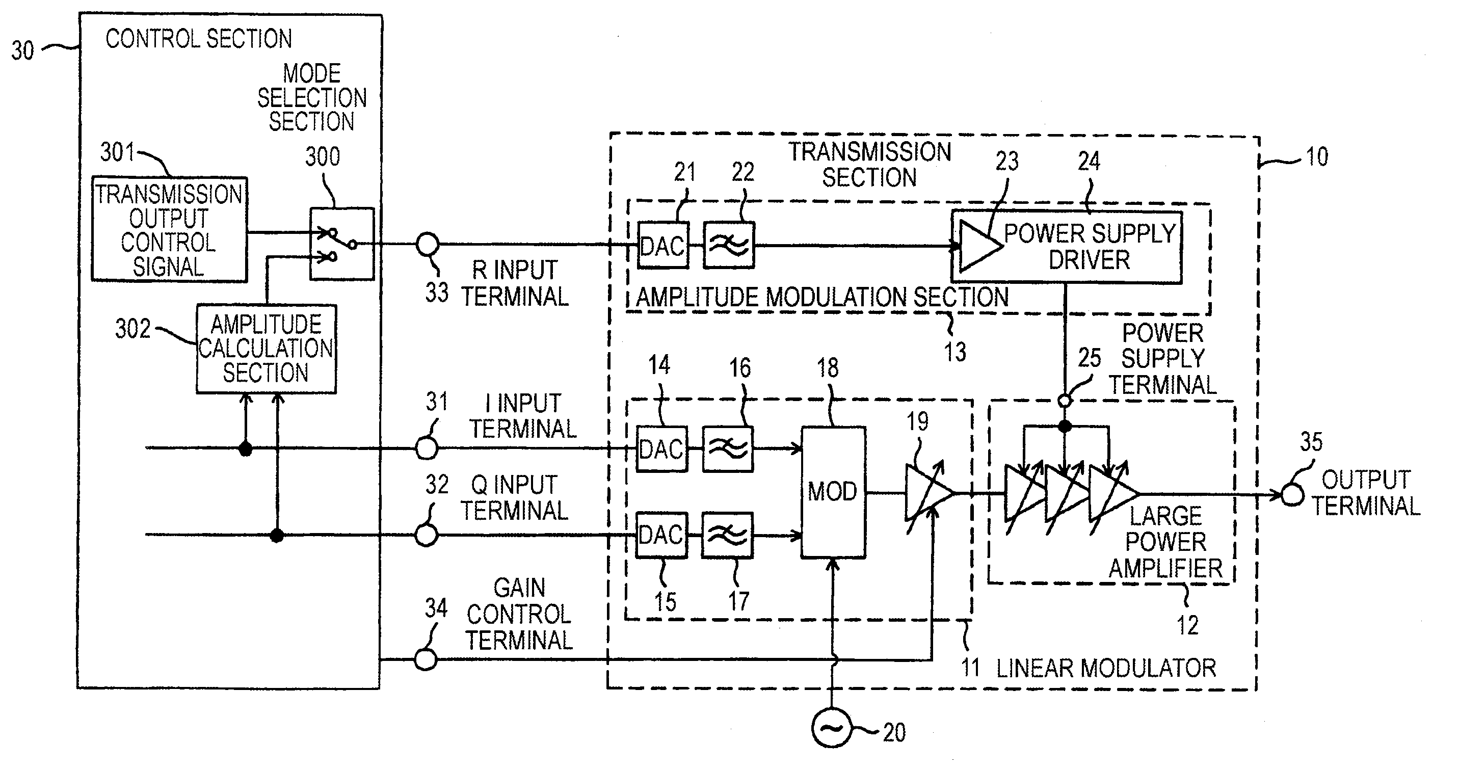
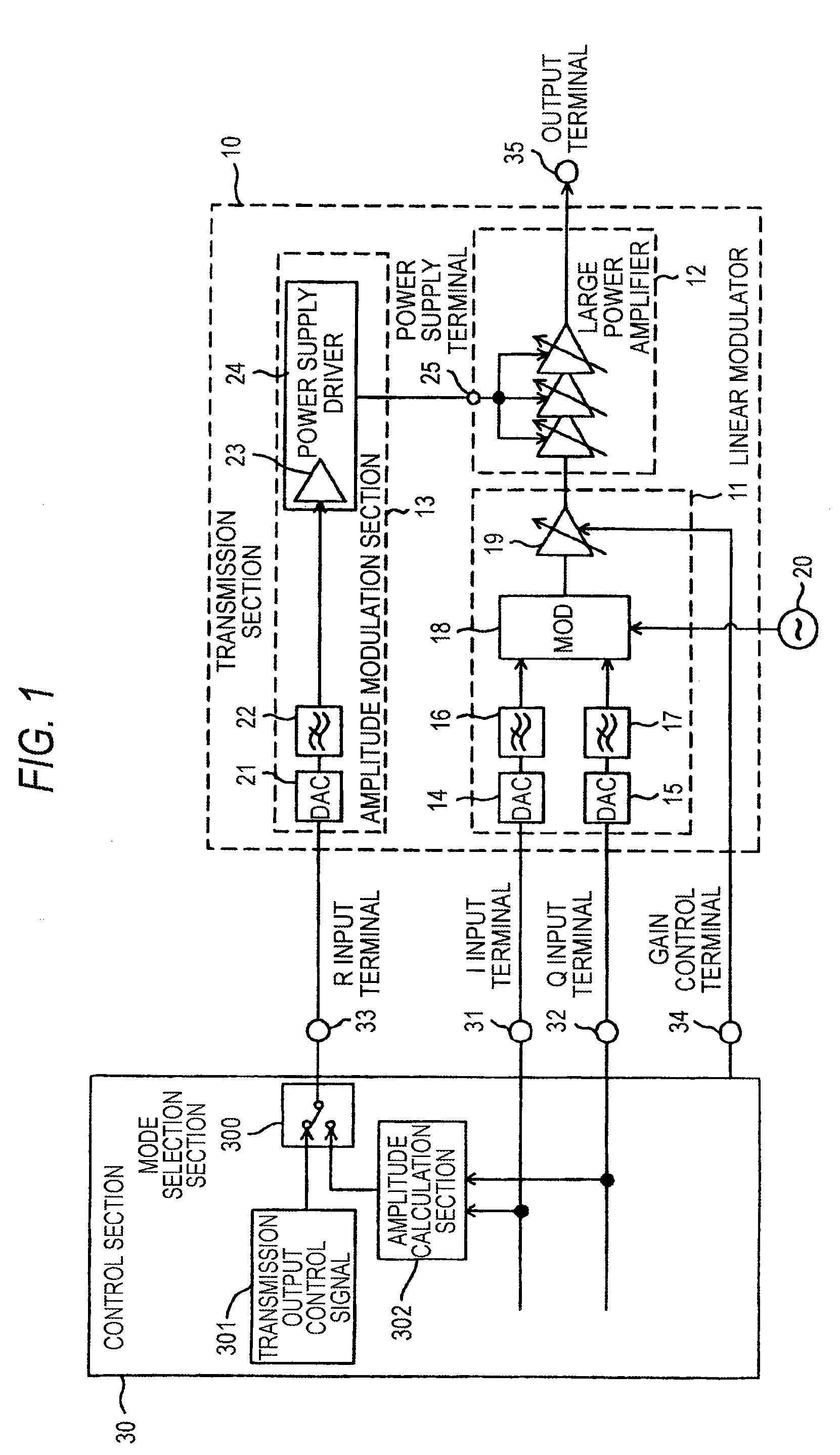
[0049]FIG. 1 is a block diagram to show the configuration of a transmitter according to a first embodiment of the invention. A transmission section 10 implementing the transmitter of the first embodiment includes a linear modulator 11, a large power amplifier 12 for performing power amplification of a transmission signal output from the linear modulator 11, and an amplitude modulation section 13 for generating power supplied to the large power amplifier 12.

[0050]The linear modulator 11 includes fixed clock input DA converters (DACs) 14 and 15 for executing digital-analog conversion according to an operation clock of a fixed frequency, low-pass filters (LPFs) 16 and 17, a quadrature modulator (MOD) 18 for executing quadrature modulation of outputs of the low-pass filters 16 and 17 at the output frequency of a local oscillator 20 and executing frequency conversion to an RF band, and a medium power amplifier 19 for amplifying output of the quadrature modulator 18.

[0051]The amplitude mo...

second embodiment

[0071]FIG. 5 is a block diagram to show the configuration of a transmitter according to a second embodiment of the invention. A transmission section 40 of the second embodiment differs from the transmission section of the first embodiment in part of the configuration; the configuration of the amplitude modulation section is changed, a clock switch terminal 36 is provided, and it is made possible to control operation current by changing an operation clock of a DA converter.

[0072]An amplitude modulation section 41 includes a variable clock input DA converter (DAC) 42 that can change the operation clock according to a switch signal from the clock switch terminal 36 in a transmission output control signal input section. Other components are similar to those of the first embodiment and similar components are denoted by the same reference numerals and will not be discussed again.

[0073]The variable clock input DA converter 42, which has an operation clock switch function, can change the op...

third embodiment

[0076]FIG. 6 is a block diagram to show the configuration of a transmitter according to a third embodiment of the invention. A transmission section 50 of the third embodiment differs from the transmission section of the second embodiment in part of the configuration; the configuration of the amplitude modulation section is changed, a current switch terminal 37 is provided, and it is made possible to control operation current of a high-speed operational amplifier of a power supply driver.

[0077]An amplitude modulation section 51 has a power supply driver 53 including a high-speed operational amplifier (OPAMP) 52 that can change the operation current according to a switch signal from the current switch terminal 37 in an input section. Other components are similar to those of the first and second embodiments and similar components are denoted by the same reference numerals and will not be discussed again.

[0078]The high-speed operational amplifier 52, which has an operation current switc...


PUM


Abstract

A transmitter providing a wide output control variable width with high efficiency is provided. Saturation mode operation is performed in the vicinity of the maximum transmission power and the input level of a large power amplifier is enlarged and fixed. When the large power amplifier is operated in a saturation state, the amplitude component of a modulation signal is input to an R input terminal in the range responsive to an output power control level and power supply voltage of a power supply terminal is amplitude-modulated, whereby highly efficient polar coordinate modulation is performed. In smaller transmission power, linear mode operation is performed, the input level of the large power amplifier is lessened for operating the large power amplifier in the linear mode, and the power supply voltage of the power supply terminal is made variable in response to the output power control level, whereby transmission power control is performed.

Description

TECHNICAL FIELD[0001]This invention relates to a transmitter whose output can be controlled variably and a wireless communication apparatus using the transmitter.BACKGROUND ART[0002]For a transmitter whose output can be controlled variably, the power efficiency and the linearity in a transmission function are evaluated as indicators for measuring the performance of the apparatus. The power efficiency and the linearity in the transmission function are the most important indicators to represent the performance of the apparatus particularly in a high-frequency modulation transmission machine such as a mobile telephone.[0003]An amplifier of class A operation is widely used as an amplifier at the last stage of such a high-frequency modulation transmission machine. The class A amplifier has small distortion, namely, is excellent in linearity, but provides small power efficiency because it consumes power accompanying a DC bias component at all times.[0004]Then, designed as a method of oper...

Claims


Application Information

Patent Timeline
Patent Type & Authority Patents(United States)
IPC IPC(8): H04L25/49H03F1/26H04L27/20H04B1/02H03F1/02H03F3/189H03F3/24H03G3/00H03G3/30H04B1/04H04B7/005H04L27/36
CPCH03F1/0227H03G3/004H03G3/3042H03G3/3052H04B1/04H04L27/361H04L27/366H03F2200/372H04B2001/045H04W52/52H03F1/02H03F3/24
Inventor SAITO, NORIAKITANAKA, KOICHIROTANABE, MITSURU
Owner PANASONIC CORP
Why Eureka
Try Eureka