
X-ray tomograph

a tomograph and x-ray technology, applied in tomography, instruments, nuclear engineering, etc., can solve the problems of data redundancy changing from one pixel to another in a complicated manner, poor data utilization rate, and large time width of voxels, so as to improve image quality, shorten time width, and improve time resolution for each voxel

Active Publication Date: 2010-03-23
FUJIFILM HEALTHCARE CORP
View PDF17 Cites 3 Cited by
  • Summary
  • Abstract
  • Description
  • Claims
  • Application Information

AI Technical Summary

Benefits of technology

The present invention is a tomograph that uses a radiation source and a radiation detector to create a three-dimensional image of an object. The tomograph includes a reconfiguration means that creates a three-dimensional image by detecting the radiation beams that pass through the examinee and the bed on which the examinee is placed. The reconfiguration means determines the projection data range for each voxel in the image so that the angle of the radiation beams is the same at both ends of the projection data range. This ensures that the data has the same quality at both ends of the projection data range. The tomograph also uses a filter to determine the optimal back projection range for each voxel, which reduces distortion and allows for the use of a single expression for redundancy corrections. The tomograph can create high-quality images quickly and accurately.

Problems solved by technology

The Feldkamp method is an image reconfiguration method for image taking of a circular orbit and is not applicable to image taking of a spiral orbit.
The Wang method is an image reconfiguration method for image taking of a spiral orbit and can correct influences of movement of an examinee, which is practiced by the conventional two-dimensional back projection method by extending the back projection phase width beyond π (increasing data redundancy), but results in a poor data utilization rate and the pitch (hereinafter referred to as “measuring throughput”) of the spiral during image taking needs to be very small.
Furthermore, it is also necessary to consider the beam width in the body axis direction and in this way data redundancy changes from one pixel to another in a complicated manner.
One of problems of these conventional three-dimensional reconfigurations is an increase in a calculation time.

Method used


Image

  • X-ray tomograph
  • X-ray tomograph
  • X-ray tomograph

Examples


embodiment 1

[0071]With reference now to the attached drawings, embodiments of the present invention will be explained in detail below.

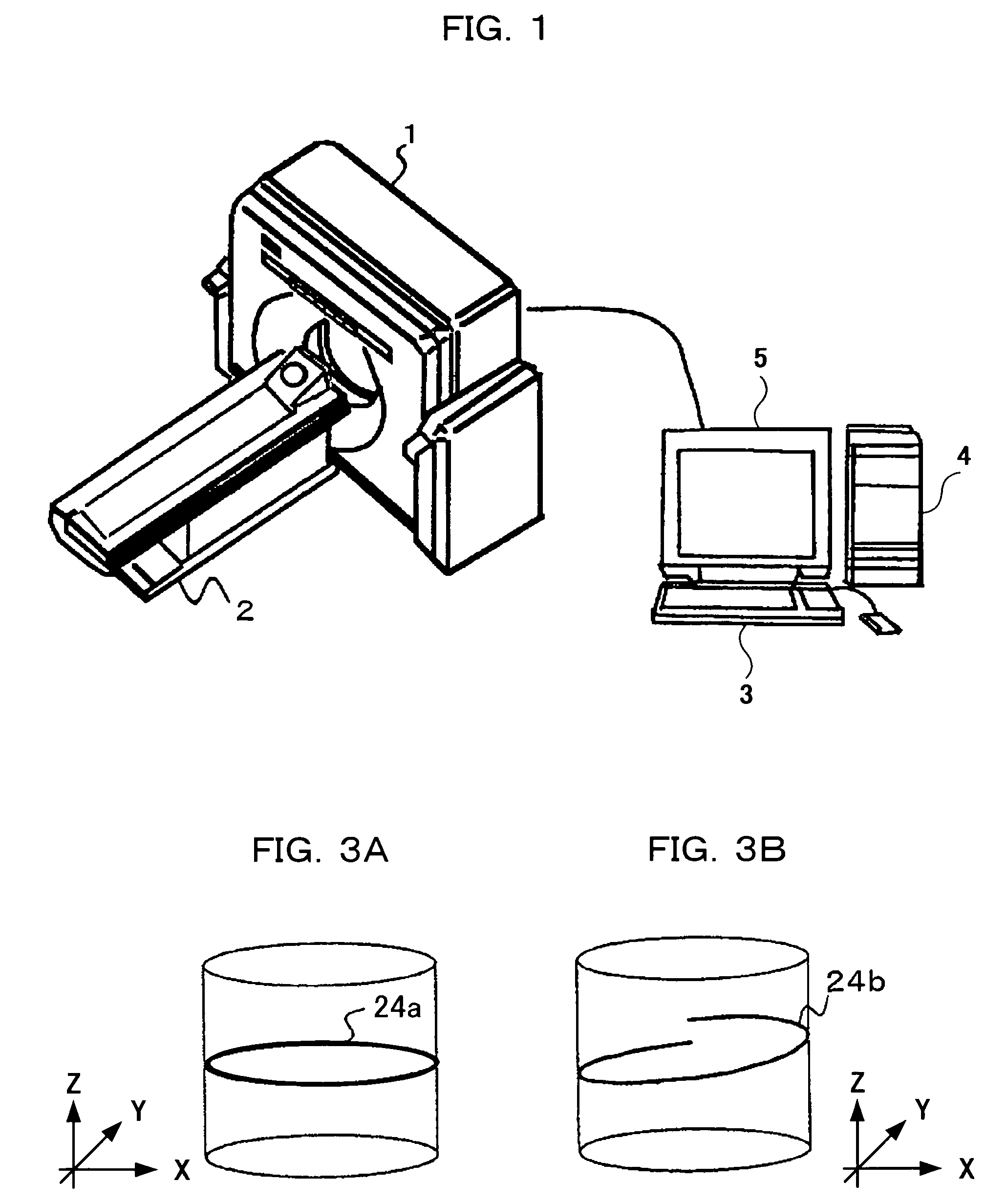
[0072]FIG. 1 is a schematic outside view of a tomograph according to an embodiment of the present invention. The tomograph comprises a scanner 1 used for image taking, a bed 2 to place and move an examinee, an input device 3 made up of a mouse and keyboard, etc., for inputting measuring reconfiguration parameters such as bed moving speed information and reconfiguration position, a calculation device 4 for processing data obtained from a multi-row detector and a display device 5 which displays a reconfigured image.

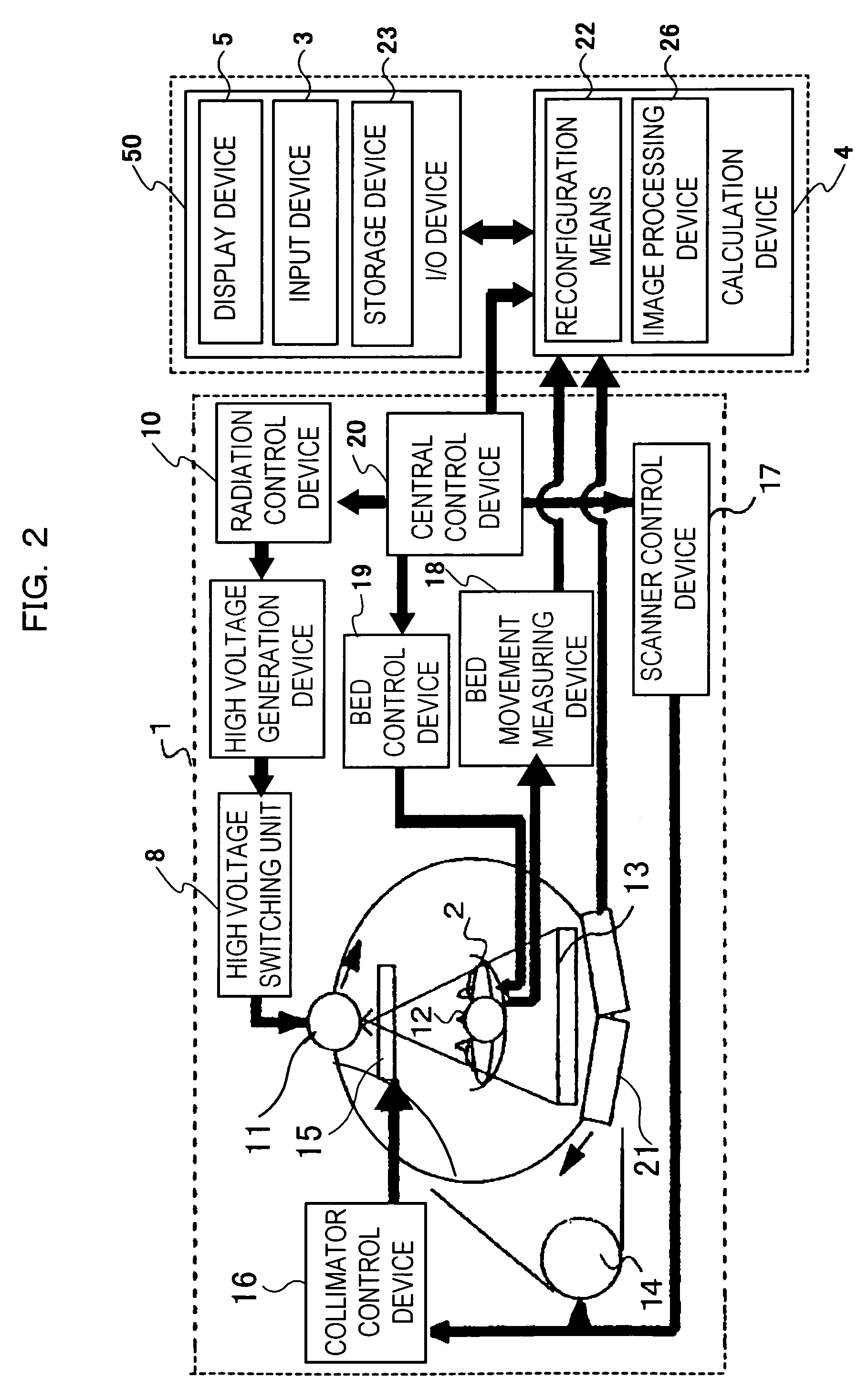
[0073]FIG. 2 is a block diagram of the tomograph shown in FIG. 1.

[0074]The scanner 1 consists of a bed 2, a high voltage switching unit 8, a high voltage generation device 9, a radiation source 11 such as a radiation generation device having a radiation control device 10, a radiation detector 13 placed opposite to the radiation source 11 with respect to ...

embodiment 2

[0120]FIG. 16 is a flow chart showing a processing operation of the reconfiguration means 22 according to another embodiment of the present invention.

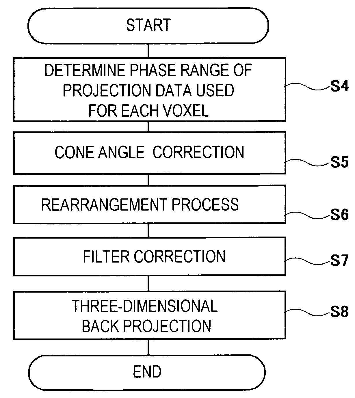
[0121]In this embodiment, a filter correction is performed in step S7 shown in FIG. 9, and then redundancy correction weighting is performed in step S9 and three-dimensional back projection is performed in step S8.

[0122]In the case of this embodiment, the reconfiguration means further includes redundancy correction weighting means for realizing a redundancy correction using a weighting function whose shape changes according to the phase width with respect to filter-processed projection data over a projection data range fπ determined and obtained by the operating data phase range means.

[0123]Processes in steps S4 to S8 are the same as the procedure already explained using FIG. 9 and therefore a weighting process using the redundancy correction weighting means in step S9 will be explained here.

[0124]As shown in FIGS. 17 to 19, data of 18...

embodiment 3

[0128]FIG. 23 is a flow chart showing a processing operation of reconfiguration means 22 according to a further embodiment of the present invention.

[0129]As shown in FIG. 23, after processes in step S4 and step S5, this embodiment carries out a rearrangement process on projection data of an image taken with a view of a multiple of 4 in step S11. Then, in step S7, a filter correction is performed and in step S12, projection data whose phase in the go-around direction differs by Nπ / 2 (N=1, 2, 3, . . . ) [rad] is grouped by grouping means and in step S9, a redundancy correction weighting process is carried out and in step S8, the grouped projection data is back projected to a square image group by group.

[0130]In order to realize such processing, means for acquiring projection data whose number of images taken per rotation is a multiple of 4 is provided, the reconfiguration means 22 includes means for superimposing a filter on this projection data, grouping means for grouping data at th...


PUM


Abstract

A tomograph which determines projection data phase range capable of back projection for each reconfigured voxel with an arbitrary value larger than π so that the absolute values of cone angles at the ends of this phase range is minimized, calculates an approximate straight line for a curve indicating the position of a radiation source with respect to the channel direction position of parallel beam projection data obtained by a parallel beam of a parallel shape viewed from the go-around axis direction generated from the radiation source, and based on the determined projection data range capable of back projection, three-dimension back projects the parallel beam projection data subjected to filter processing created through a filter correction to the back projection region corresponding to the region in concern along the approximate irradiation trace of the radiation beam calculated using the calculated approximate straight line, thereby suppressing generation of the distortion attributed to data discontinuity, simplifying an arcsin calculation and significantly increasing the processing speed of the tomograph.

Description

TECHNICAL FIELD[0001]The present invention relates to a tomograph which generates a tomographic image of an examinee using projection data obtained from a radiation source moving in the body axis direction relative to the examinee through a radiation detector.BACKGROUND ART[0002]A conventional three-dimensional back projection method will be explained. A Feldkamp method, Wang method, IHCB method and PI-method proposed as three-dimensional back projection methods are three-dimensional back projection methods which capture a cone beam spreading (having an angle of inclination) in both the slice (body axis) direction and channel (rotation) direction irradiated to multi-row radiation detectors as a collection of a plurality of rows of fan beams spreading only in the channel direction, carry out filter correction processing similar to a two-dimensional back projection method on the fan beam projection data obtained from each detector row or parallel beam projection data obtained by repla...

Claims


Application Information

Patent Timeline
Patent Type & Authority Patents(United States)
IPC IPC(8): A61B6/03G06T11/00
CPCA61B6/032G06T11/005A61B6/027A61B6/4085G06T2211/421
Inventor GOTO, TAIGAMIYAZAKI, OSAMUHIROKAWA, KOICHI
Owner FUJIFILM HEALTHCARE CORP
Learn More