Method of producing a ceramic matrix composite article

a ceramic matrix and composite material technology, applied in the direction of coatings, liquid surface applicators, pretreated surfaces, etc., can solve the problems of inability to accurately machine, inability to produce acceptable impression patterns, and difficulty in achieving accurate machine accuracy, so as to promote the adhesion of the coating, the robustness of the coating can be enhanced, and the effect of sufficient robustness

Inactive Publication Date: 2010-03-30
GENERAL ELECTRIC CO
View PDF14 Cites 23 Cited by
  • Summary
  • Abstract
  • Description
  • Claims
  • Application Information

AI Technical Summary

Benefits of technology

[0008]According to a preferred aspect of the invention, the coating is sufficiently robust to withstand commercial CNC machining and inspection by metrology equipment. The robustness and compatibility of the coating can be enhanced by forming the slurry thereof of the same or similar materials used to make the body, including its reinforcement and matrix materials. According to a preferred aspect of the invention, the body is infiltrated with a suitable infiltration material prior to depositing, curing, and machining of the coating, and thereafter melt infiltrated. For the melt infiltration step, the body can be placed in a tool and melt infiltrated while the coating contacts and conforms to a die surface of the tool, during which the melt infiltrant reacts to form the desired ceramic matrix material. During the melt infiltration operation, the coating is also preferably infiltrated with the melt infiltrant, whose conversion to the ceramic matrix material promotes the adhesion of the coating to the underlying CMC substrate of the article. Depending on the melt infiltrant, the carbon constituent within the coating can promote wetting by the melt infiltrant to ensure complete infiltration of the coating, as well as fill any spaces between the surfaces of the coating and die to more fully and reliably obtain the desired net shape of the article.
[0009]In view of the above, it can be seen that a significant advantage of this invention is that, because the coating provides a barrier between the reinforcement material of the body and the surface of the die, imprint patterns and other potential surface flaws resulting from the reinforcement material and processing of the body are avoided. In so doing, the coating is largely responsible for producing the final shape, dimensions, and surface of the CMC article. Because machining of the coating is performed in the green state, the coating can be more readily machined to a very near net-shape than would be possible if attempting to machine the much harder material of the final CMC substrate.

Problems solved by technology

Depending on the intended application of the article, an imprint pattern may be unacceptable, such as where the article is required to have an optical surface, defined herein as a surface that is sufficiently smooth to be suitable for bonding to, for example, a silicon wafer.
However, such attempts often do not produce acceptable results because the resulting coating is very fragile and thus difficult to accurately machine for the purpose of establishing the desired shape and dimensions of the CMC article and its optical surface.
However, the slurry is too soft to permit machining to high tolerances.

Method used


Image

  • Method of producing a ceramic matrix composite article
  • Method of producing a ceramic matrix composite article
  • Method of producing a ceramic matrix composite article

Examples


Embodiment Construction

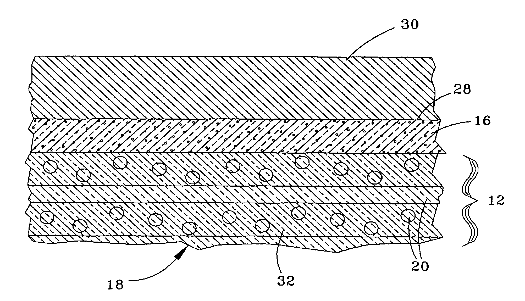
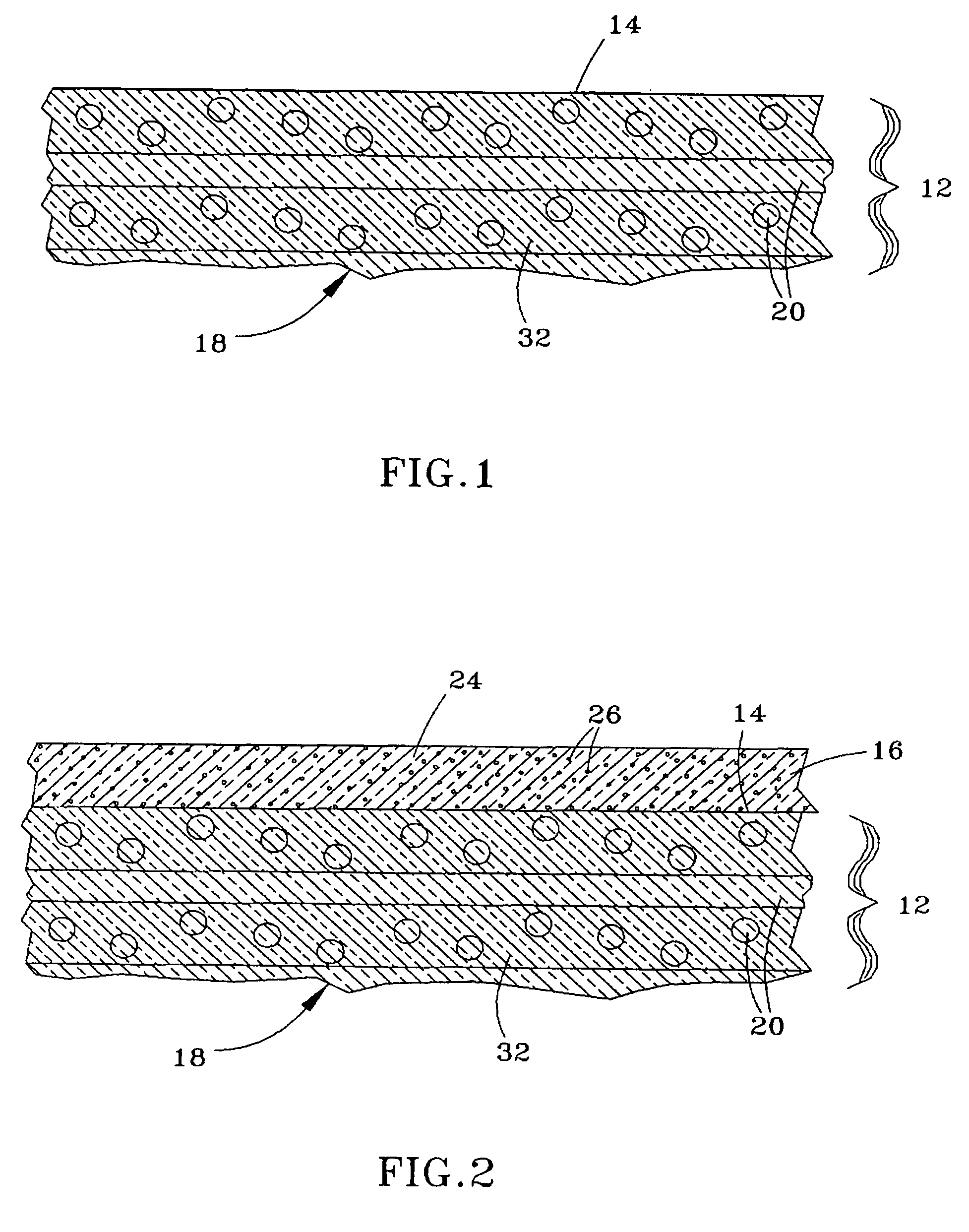
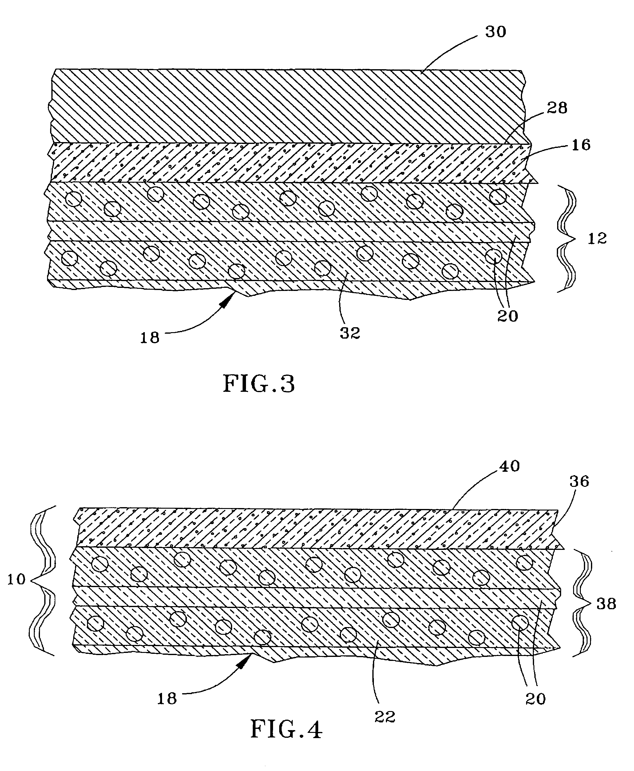
[0015]FIGS. 1 through 4 represent cross-sectional views of a surface portion of a body undergoing processing steps to produce a CMC article 10 (FIG. 4) in accordance with a preferred embodiment of the invention. As a CMC, the article 10 comprises a ceramic matrix 22 reinforced with a ceramic reinforcement fabric 18 made up of individual continuous tows 20 (bundles of continuous fibers). In a preferred embodiment, the reinforcement material 20 and the matrix 22 are formed of or at least comprise silicon carbide (SiC). Also in the preferred embodiment, the matrix 22 is formed by a silicon MI process, such that the matrix 22 further contains some free silicon. As such, the article 10 may be referred to as a SiC / Si—SiC (fiber / matrix) CMC, in accordance with the teachings of commonly-assigned U.S. Pat. Nos. 5,015,540, 5,330,854, 5,336,350, 5,628,938, and 6,024,898 and commonly-assigned U.S. Patent Application Publication No. 2004 / 0067316, whose disclosures relating to compositions and pr...


PUM

PropertyMeasurementUnit
diametersaaaaaaaaaa
particle sizeaaaaaaaaaa
thicknessaaaaaaaaaa

Abstract

A method of producing a CMC article having a net shape, and by which the article can be formed to have an exterior surface with desirable characteristics, such as being free of an imprint pattern of a fiber reinforcement material within the article. The method entails providing a body comprising the fiber reinforcement material, and depositing a coating on a surface of the body. The coating contains a carbonaceous binder and a slurry containing a ceramic particulate material. Following its deposition, the carbonaceous binder within the coating is cured to render the coating machinable, and the coating is then machined to approximately produce the net shape of the article.

Description

BACKGROUND OF THE INVENTION[0001]The present invention generally relates to ceramic matrix composite (CMC) materials. More particularly, this invention is directed to methods of forming a CMC article having desired shape, dimensional, and surface characteristics, such as those required to produce a suitable bonding surface.[0002]CMC materials generally comprise a ceramic fiber reinforcement material embedded in a ceramic matrix material. The reinforcement material serves as the load-bearing constituent of the CMC, while the ceramic matrix protects the reinforcement material, maintains the orientation of its fibers, and serves to dissipate loads to the reinforcement material. Of particular interest to high-temperature applications are silicon-based composites, such as silicon carbide (SiC) as the matrix and / or reinforcement material. SiC fibers have been used as a reinforcement material for a variety of ceramic matrix materials, including SiC, TiC, Si3N4, and Al2O3. Continuous fiber ...

Claims


Application Information

Patent Timeline
Patent Type & Authority Patents(United States)
IPC IPC(8): B05D1/12B05D3/02
CPCC04B35/573C04B35/806C04B41/009C04B41/488C04B41/83C04B41/459C04B41/5059C04B41/53C04B35/565C04B35/80
Inventor GRAY, PAUL EDWARD
Owner GENERAL ELECTRIC CO
Why Eureka
Try Eureka