Multi-band antenna system

a multi-band antenna and antenna technology, applied in the field of antenna technology, can solve the problems of large horn antenna weight, high frequency communication, and limited conventional aircraft antenna systems for satellite communication

Active Publication Date: 2010-03-30
ROCKWELL COLLINS INC
View PDF7 Cites 15 Cited by
  • Summary
  • Abstract
  • Description
  • Claims
  • Application Information

AI Technical Summary

Benefits of technology

[0004]Accordingly, the present invention is directed to an improved antenna system. In an embodiment of the invention, the antenna system of the present invention may be a high-gain, low-profile, wide-band antenna. Advantageously, the antenna system of the present invention may be formed as a plate providing a lightweight and low-cost structure having a planar profile which may be suitable for mounting on an aircraft. The plate may include a planar array of waveguides which may operate as low loss, wide-band reflecting elements to create a reflectarray antenna. Individual waveguides may be designed to scatter an incident field while impressing appropriate phase shifts in order to form a plane wavefront at the array aperture to produce a desired collimated signal. Additionally, waveguides may include multiple ridges to employ vertical and horizontal polarization across a wide bandwidth operable at a high frequency, such as 10 GHz to 30 GHz.

Problems solved by technology

Conventional on-board aircraft antenna systems for satellite communication are limited in many ways.
A drawback associated with the horn antenna and dielectric lens system is the weight and large form factor occupied by the horn antenna in order to receive satellite communication in high frequency bands, such as the Ku and Ka bands.
A heavy and large form factor antenna system mounted on an aircraft may affect the response and maneuverability of the aircraft, as well as increase the mechanical load on, and subsequent cost of, the positioning unit.
Additionally, a conventional antenna system for satellite communication may only support a limited bandwidth.
For example, a conventional on-board aircraft antenna system may be limited to receiving satellite communication in the Ka band.
In order to receive communication in the Ku band, a separate antenna and receiver system may be required, which further increases the weight, profile and form factor of the aircraft communication system.

Method used


Image

  • Multi-band antenna system
  • Multi-band antenna system
  • Multi-band antenna system

Examples


Embodiment Construction

[0012]Reference will now be made in detail to a presently preferred embodiment of the invention, an example of which is illustrated in the accompanying drawings.

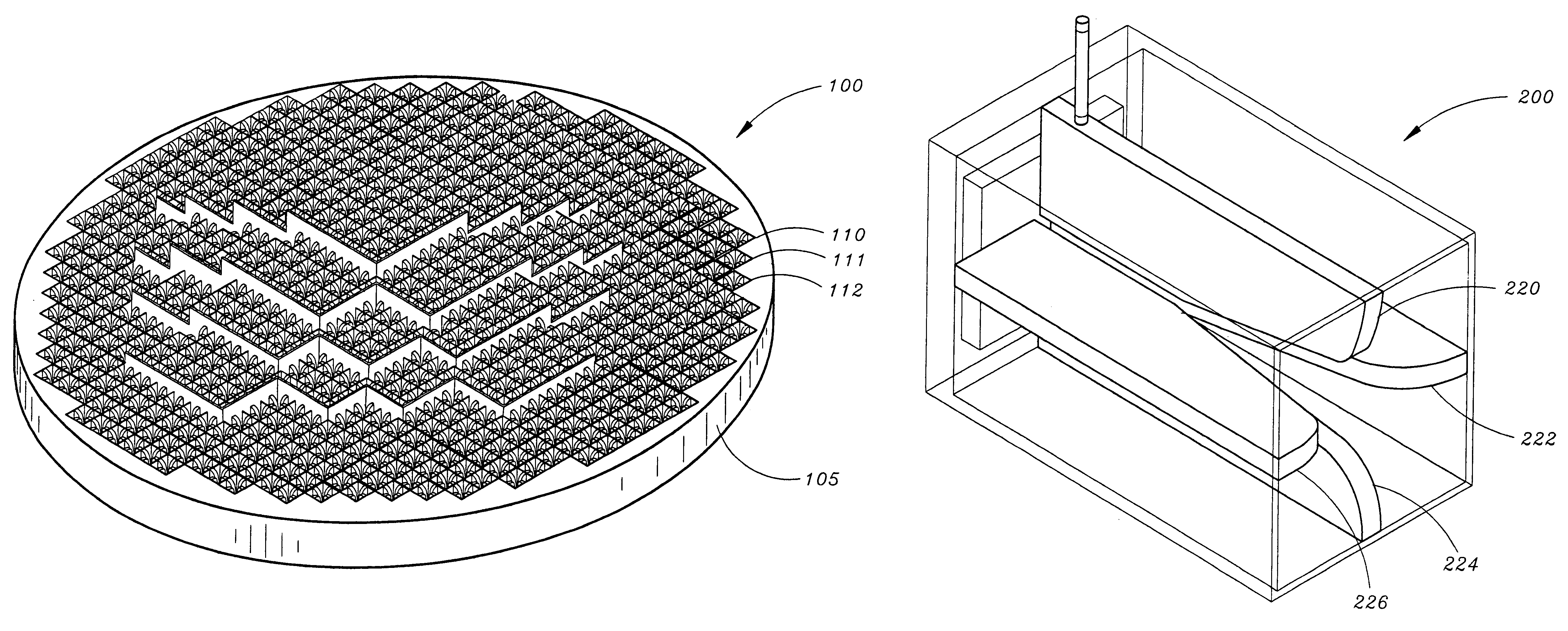
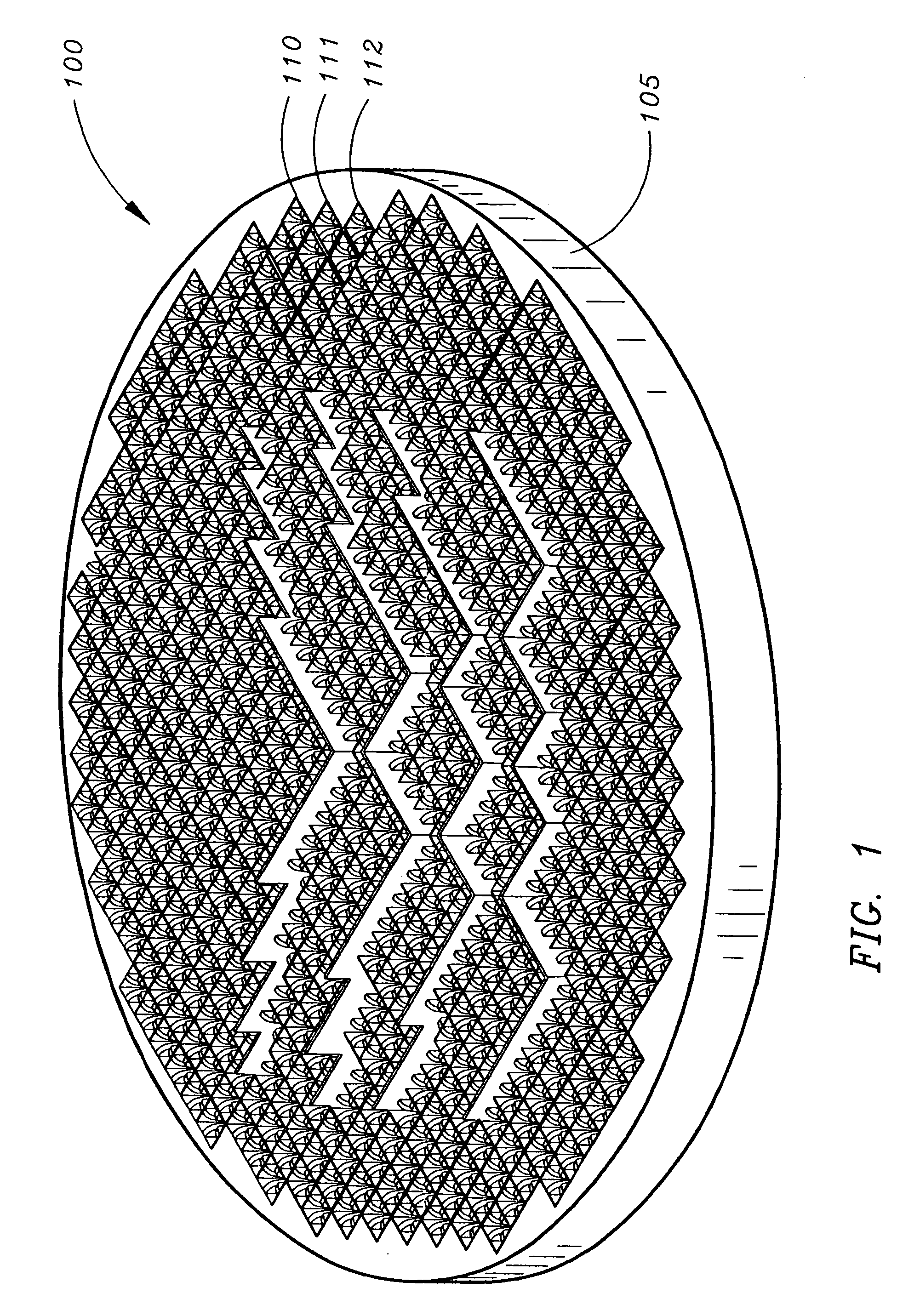
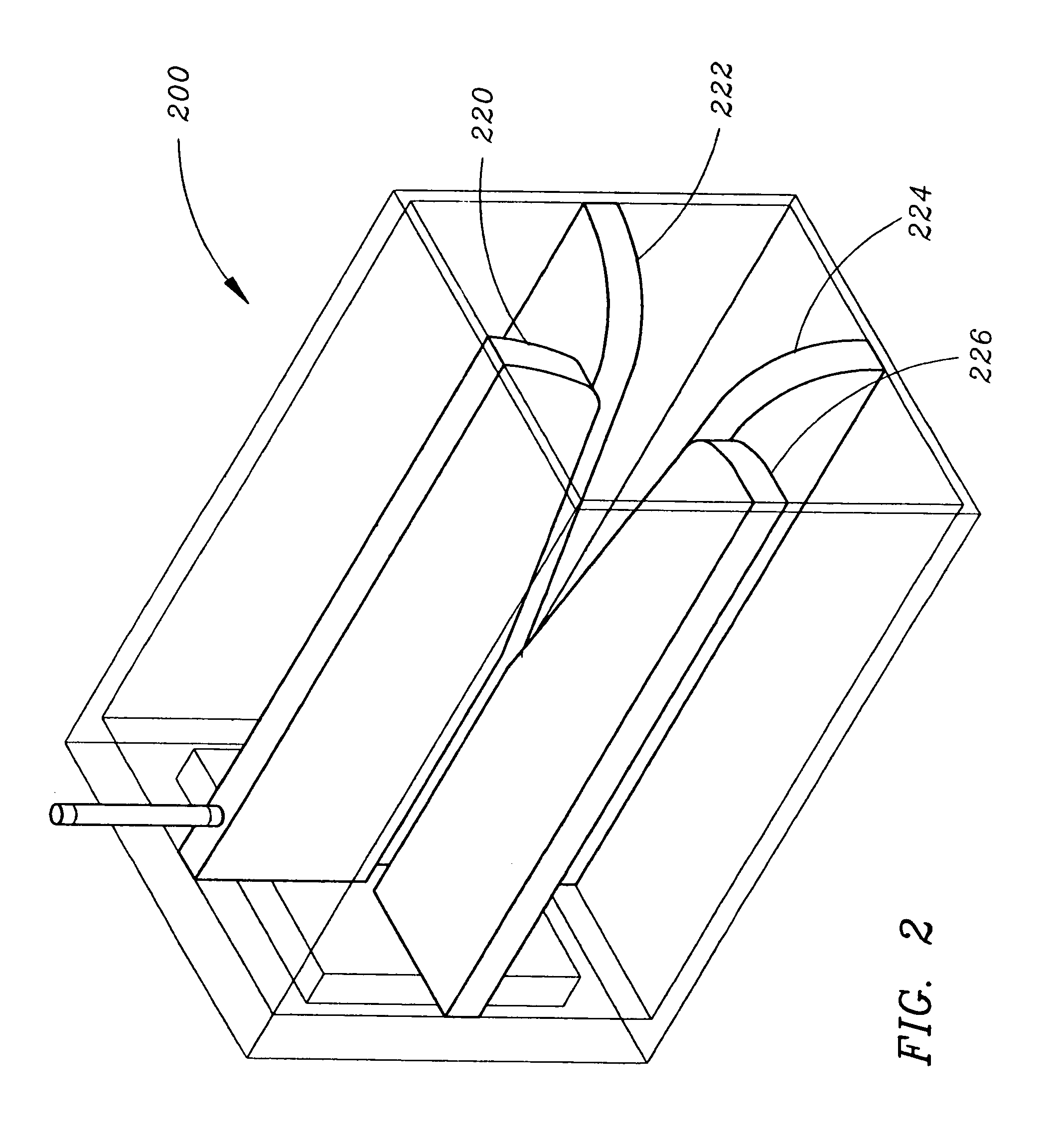
[0013]Referring generally to FIGS. 1-5, an embodiment of an antenna system in accordance with the present invention is shown. The antenna system of the present invention may be a high-gain, low-profile, wide-band antenna. Advantageously, the antenna system of the present invention may be formed as as a plate providing a flat profile, lightweight and low-cost structure which may be suitable for mounting on an aircraft. The plate may include a planar array of waveguides which may operate as low loss, wide-band reflecting elements to create a reflectarray antenna. Individual waveguides may be designed to scatter an incident field while impressing appropriate phase shifts in order to form a phase front at the array aperture to produce a desired collimated beam in the far field. Waveguides may include ridges to employ vertical an...


PUM


Abstract

The present invention is an improved antenna system. In an embodiment of the invention, the antenna system of the present invention may be a high-gain, low-profile wide-band antenna. Advantageously, the antenna system of the present invention may include a plate with reflecting elements to form a reflectarray antenna suitable for mounting on an aircraft. The reflectarray antenna of the present invention may be formed from a planar array of waveguides which may operate as a low loss, wide-band reflecting elements. Individual waveguides may be designed to scatter an incident field while impressing appropriate phase shifts in order to form a plane wavefront at the array aperture to produce a desired output signal. Waveguides may include ridges to employ vertical and horizontal polarization across a wide bandwidth operable at a high frequency, such as 10 GHz to 30 GHz.

Description

FIELD OF THE INVENTION[0001]The present invention relates generally to antenna technology, and more particularly to a multi-band antenna system.BACKGROUND OF THE INVENTION[0002]The proliferation of satellite imagery, electronic data transfer and electronic data storage has increased demand for multi-media connectivity for military and commercial aircraft applications. In a military application, real-time surveillance imagery obtained from manned and un-manned aircraft may be passed to ground troops through satellite communication. In commercial aircraft applications, many passengers of a commercial aircraft flight desire to work while on-board the flight. In order to fulfill this demand, airliners have begun offering multi-media access to aircraft passengers through satellite communication.[0003]Conventional on-board aircraft antenna systems for satellite communication are limited in many ways. For example, a conventional antenna system may include a horn antenna with a dielectric l...

Claims


Application Information

Patent Timeline
Patent Type & Authority Patents(United States)
IPC IPC(8): H01Q13/00
CPCH01Q13/0275H01Q15/14H01Q21/064
Inventor WEST, JAMES B.PAULSEN, LEE M.CHEN, DANIEL N.
Owner ROCKWELL COLLINS INC
Why Eureka
Try Eureka