Solar collector panel for heating ventilation air

a technology of solar collectors and solar collectors, which is applied in the field of solar collectors, can solve the problems of no longer effective convection insulation, and achieve the effect of improving the reliability of photovoltaic cell cooling and simplifying the manufacturing of solar collector panels

Active Publication Date: 2010-04-13
NORTON CHRISTENSEN INC
View PDF14 Cites 6 Cited by
  • Summary
  • Abstract
  • Description
  • Claims
  • Application Information

AI Technical Summary

Benefits of technology

[0008]The invention provides a solar collector panel with a construction that simplifies the manufacturing of the solar collector panel and secondarily improves the reliability of the cooling of a photovoltaic cell panel arranged within the solar collector panel.
[0010]The space between the permeable back panel and the permeable heat absorber means serve as a thermal insulation while the solar collector panel is operating and thus replacing the thermal insulation material used in the art, such as rock wool panels. The substantially uniformly distributed airflow from the colder back panel to the warmer heat absorber means has a direction opposite the temperature gradient and prevents a convection heat loss from the heat absorber means. Heat loss due to radiation in the infrared spectrum from the heat absorber means is effectively reduced by the back panel, which reflects a part of the radiation back to the heat absorber means and absorbs the remaining part as heat energy, which is returned into the solar collection panel by the cold air flowing through the permeable back panel from the surroundings.
[0011]The pressure drop of the airflow over the back panel promotes the homogeneity of the airflow distribution over the area spanned by the solar collector panel. This provides the advantage that the airflow velocities are generally low in most of the solar collector panel, with the possible exception of the area close to the outlet, even for solar collector panels spanning a large area or more solar collector panel coupled to each other, as opposed to the traditional solar collector panels having one common air inlet and a generally high velocity of the air. Low velocities means low pressure losses and low generation of noise, and the low air velocity at the intake of air into the solar collector panel, i.e. at the back side of the back panel, has the further effect that only small dust particles are carried with the air flow into the solar collector panel as larger and more heavy particles are less susceptible to be accelerated by the low air velocity. Thus, an air cleaning effect on the ventilation air exhausted from the solar collector panel is obtained as well and filtering of the ventilation air may be reduced or made redundant. The solar collector panel and in particular the permeable parts and the possible filters will be subjected to dust to a reduced extend, thus requiring less maintenance and cleaning of the solar collector panel.
[0012]A further advantage of the construction of a solar collector panel according to the invention is that it is particularly suitable for having a photovoltaic cell panel arranged therein, as the construction reduces the risk of excessive heating of the photovoltaic cell panel in case the airflow through the solar collector panel is stopped. When the airflow from the back panel towards the heat absorbing means stops, the thermally insulating action of the airflow is halted as well and heat may now flow from the heat absorber means out through the back panel by natural convection as well as heat radiation, and the excessive heating with stagnation temperatures of more than 120° C. known from solar collector panels with traditional thermal insulating material may be avoided.
[0016]It is advantageous to reduce the heat loss from the heat absorber means due to radiation out through the front panel. The front panel may have a coating layer on the inner side facing the heat absorber means that enhances the reflection of radiation in the infrared range, in particular of wavelengths in the range of 5 to 25 μm where most of the energy of the heat is radiated from the heat absorber means, whereas most of the energy of the solar radiation is found at lower wavelengths.
[0022]Instead of using a metal plate for the heat absorber means, it is preferred to employ a fibrous mat, in particular a screen of felt, that should have a dark colour or be black to absorb as much as possible of the solar radiation. Other types of fibrous mats may also be employed, such as woven or non-woven cloth or stamped cloth. A lower mass of the heat absorber means may be obtained by using a fibrous mat as compared to other materials, and the insulating effect is also advantageous for preventing heat from the spacing between the heat absorber means and the front panel from escaping through the back panel.

Problems solved by technology

Furthermore, in case the flow of air through the solar collector panel is stopped the convection-insulation will no longer be effective, and a photovoltaic cell panel placed within the solar collector panel and generating electricity from the solar radiation will not be subjected to the damaging high stagnation temperature of a traditionally insulated solar collector panel.

Method used


Image

  • Solar collector panel for heating ventilation air
  • Solar collector panel for heating ventilation air
  • Solar collector panel for heating ventilation air

Examples


Embodiment Construction

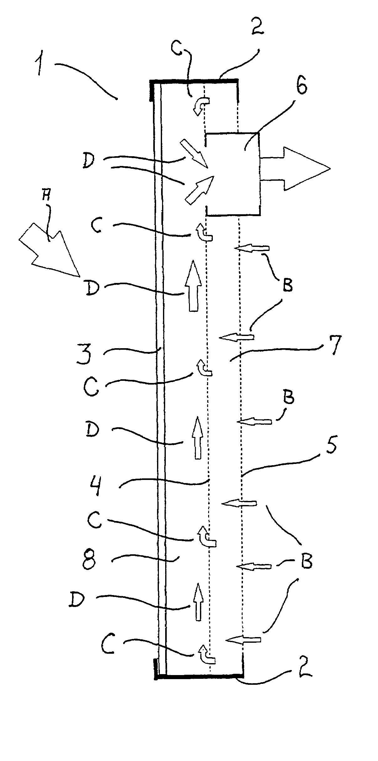
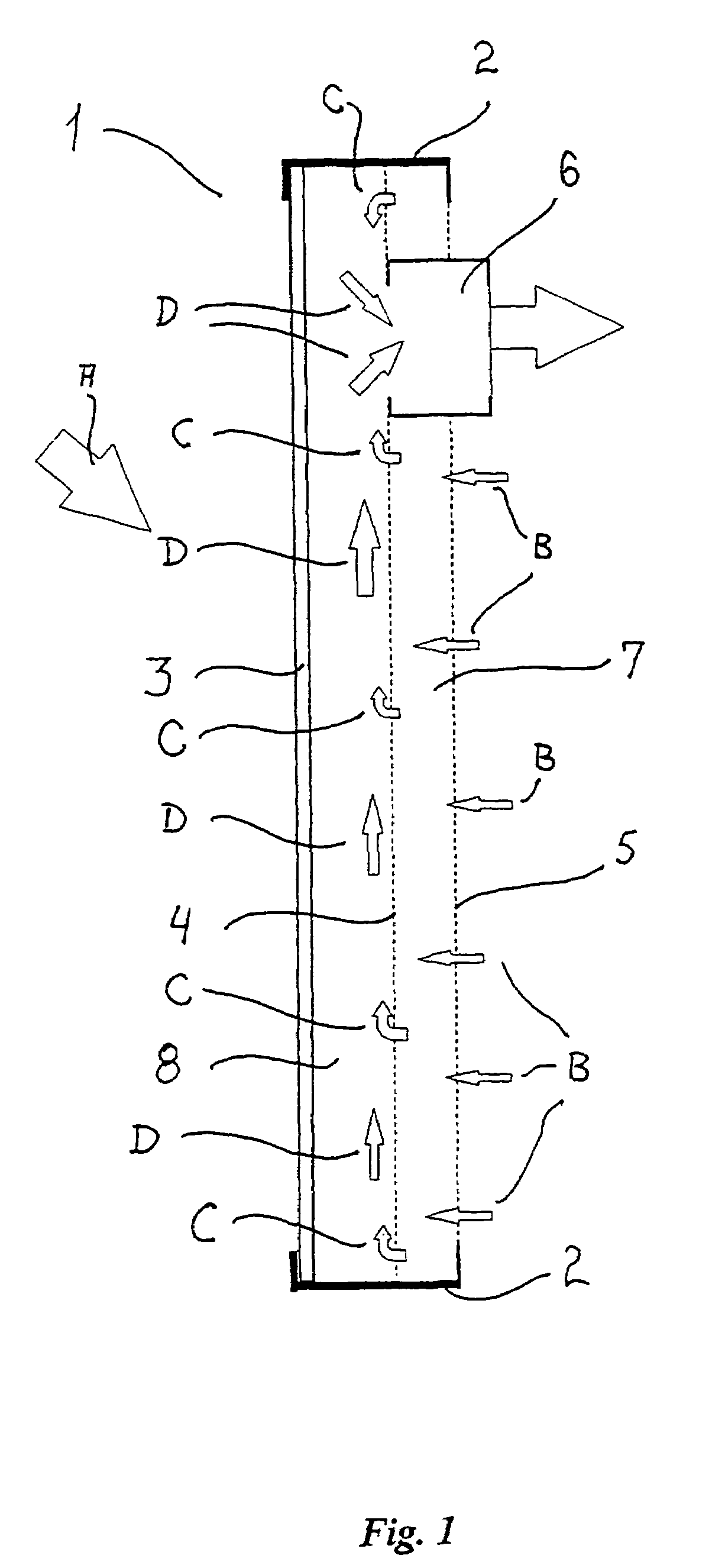
[0031]A solar collector panel 1 according to a first embodiment of the invention is shown in a longitudinal section in FIG. 1, in which an aluminium frame 2 holds a transparent front panel 3 made from a 10 millimeter plate of polycarbonate with elongated cavities defined therein to lower the weight thereof and improve the thermal insulation, a heat absorber means 4 made from a screen of black felt, and a back panel 5 made from a similar perforated aluminium sheet that is left with a blank side facing the heat absorber means 4. In an alternative embodiment, the heat absorber means 4 is made from a perforated aluminium sheet 0.7 millimeters of thickness, which is painted black or anodised on both sides. The solar collector panel 1 is preferably arranged vertically as shown, and the direction of the solar radiation is indicated with arrow A. An outlet duct 6 is arranged at the upper part of the panel 1 to form a passageway for the heated air to flow out from the panel 1 and to the plac...


PUM


Abstract

A solar collector panel is disclosed for heating of air, in which the conventional insulation material on the back panel facing away from the sun is replaced by a spacing between a permeable back panel and a permeable heat absorber means, so that a heat convection airflow through the back panel and into the interior of the solar energy panel against the temperature gradient prevents the convection heat loss in the opposite direction. The back panel also reduces the radiation heat loss from the heat absorber means. Furthermore, in case the flow of air through the solar energy panel is stopped, the convection-insulation will no longer be effective, and a photovoltaic cell panel placed within the solar energy panel and generating electricity from the solar radiation will not be subjected to the damaging high stagnation temperature of a traditionally insulated solar collector panel.

Description

TECHNICAL FIELD OF INVENTION[0001]The present invention relates to a solar collector panel for collection of thermal energy by heating of air, in which the conventional insulation material on the back panel facing away from the sun is replaced by the heat convection airflow through a permeable back panel and into the interior of the solar energy panel against the temperature gradient.[0002]Furthermore, in case the flow of air through the solar collector panel is stopped the convection-insulation will no longer be effective, and a photovoltaic cell panel placed within the solar collector panel and generating electricity from the solar radiation will not be subjected to the damaging high stagnation temperature of a traditionally insulated solar collector panel.BACKGROUND[0003]Solar collector panels for heating of water for domestic use or for space heating are well known in the art, but also solar collector panels for heating of air, either to be used directly for ventilation and spac...

Claims


Application Information

Patent Timeline
Patent Type & Authority Patents(United States)
IPC IPC(8): E04D13/18H01L31/00F24F5/00F24J2/00F24F7/06F24F7/10F24J2/04F24S10/50F24S10/80
CPCF24F5/0046F24F7/06F24J2/28F24J2/20F24F2007/004Y02E10/44F24S10/80F24S10/50
Inventor CHRISTENSEN
Owner NORTON CHRISTENSEN INC
Why Eureka
Try Eureka