Processes and devices for sterilizing contaminated objects

a technology for contaminated objects and processes, applied in the field of process and device for sterilizing contaminated objects, can solve the problems of inability to achieve significant breakthroughs in sterilization, process and device tend to damage or deteriorate the objects to be sterilized, prior art processes have limitations,

Inactive Publication Date: 2010-04-13
MOISAN MICHEL +2
View PDF12 Cites 7 Cited by
  • Summary
  • Abstract
  • Description
  • Claims
  • Application Information

AI Technical Summary

Benefits of technology

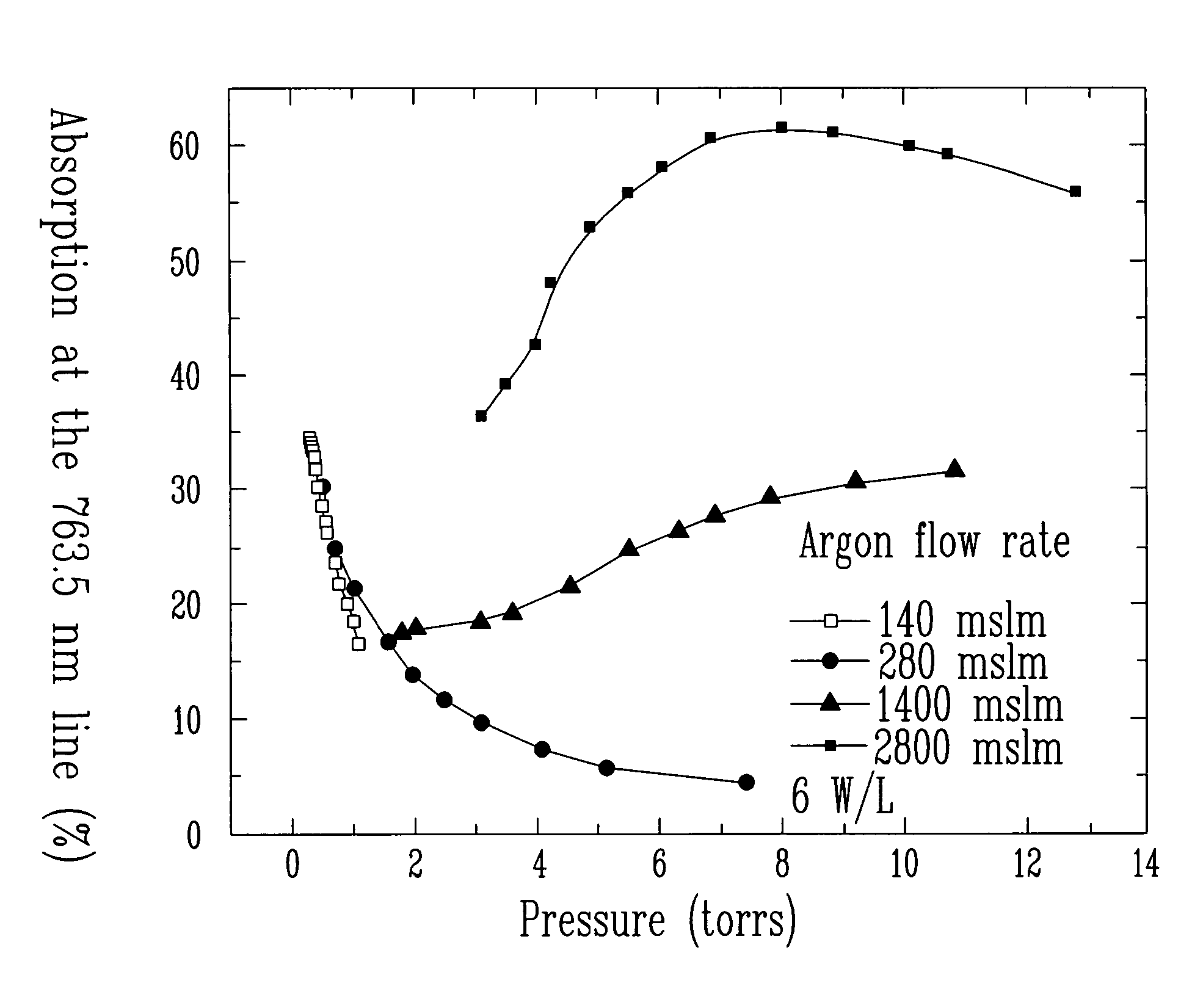
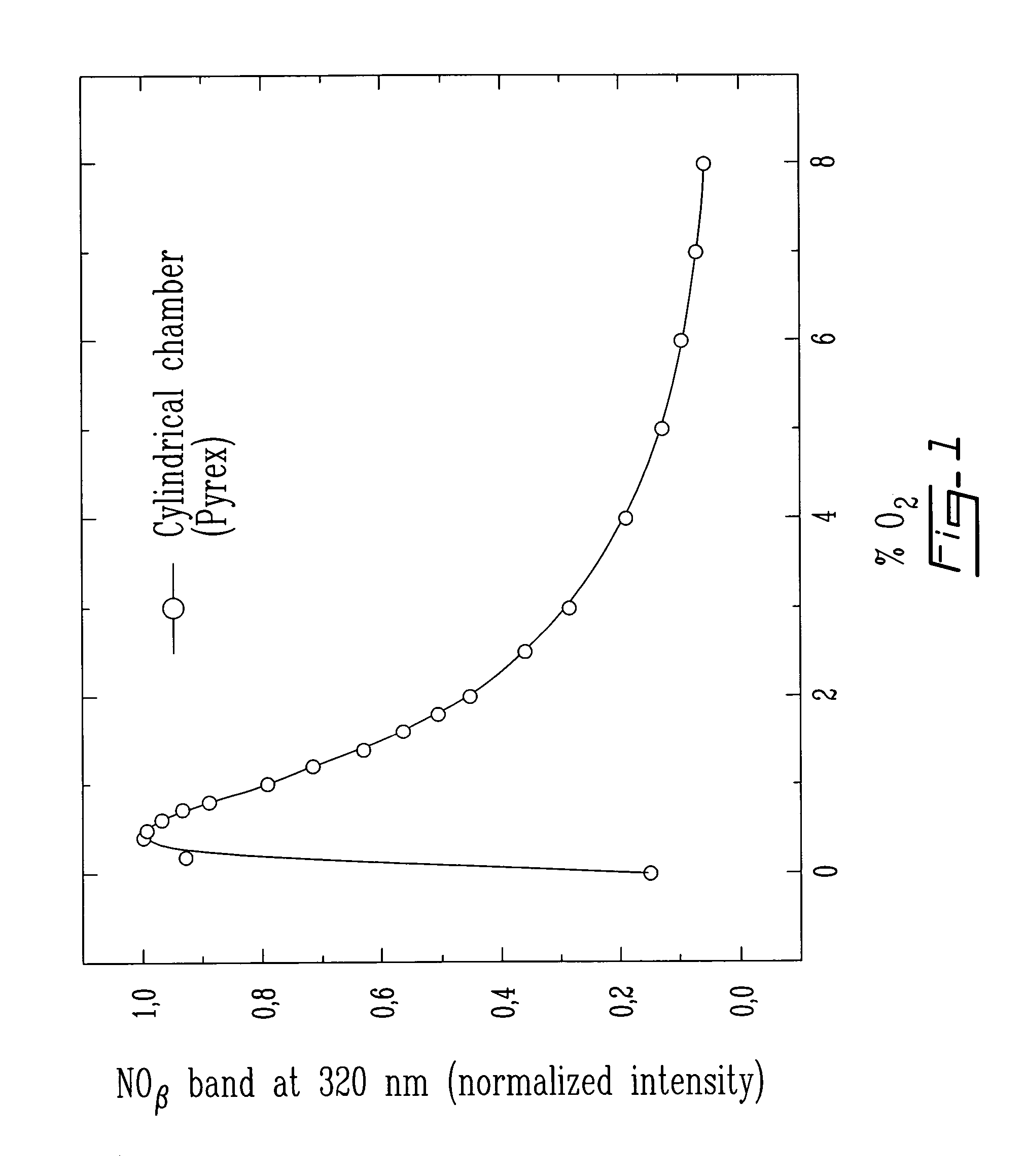
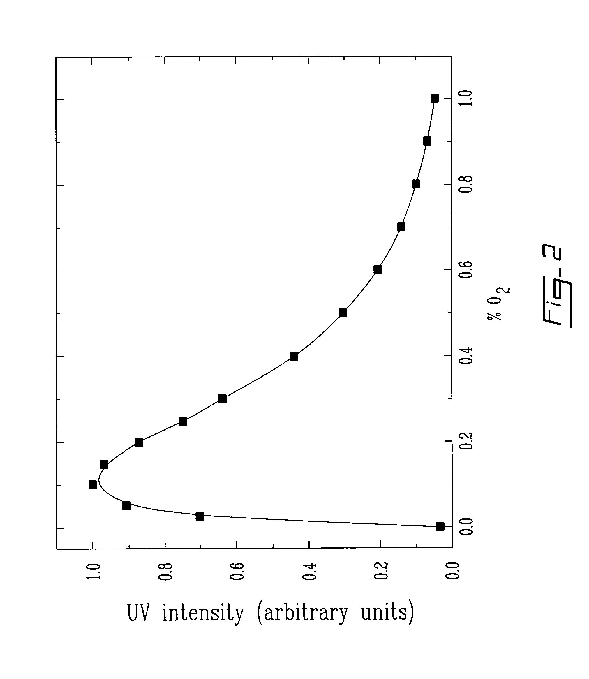
[0016]It has been found that a process, as defined in the first or second aspect of the invention, for sterilizing a contaminated object by maximizing the UV radiation intensity through the control of the flow rate and / or gas pressure in the chamber, permit to obtain improved results with respect to the sterilization. In fact, such processes have demonstrated a high performance sterilization. It has been demonstrated, for a particular gas, that by obtaining a preferred range of values of pressure (that permit to maximize the UV radiation intensity) by measuring (recording) the UV emission intensity as a function of the pressure, and / or by obtaining a preferred range of values of flow rate (that permit to maximize the UV radiation intensity) by measuring the UV emission intensity as a function of the flow rate, and by applying at least one range (and preferably both ranges) of these values (ranges of pressure and flow rate) during a sterilization process, permit to optimize the sterilization process. In fact, by applying these preferred ranges of pressure and of flow rate, which each correspond to maximized values of UV radiation intensity, the time required for obtaining sterility of the contaminated object can be considerably reduced.
[0018]It has been found that the process as defined in the third aspect of the invention was very effective for sterilizing a contaminated object. In fact, by maximizing the UV radiation intensity through control of the flow rate and / or gas pressure in the chamber, and by obtaining a ratio (CDT) / (CSC) comprised between 0.05 and 0.70, improved results with respect to the sterilization process were noted.
[0023]It has been found that by using a process as defined in the fourth aspect of the invention a high performance sterilization is obtained and deterioration or erosion of the treated object is considerably reduced. In fact, by using a gas stream consisting of helium, neon, argon, krypton, xenon, or mixtures thereof, the presence of oxidizing species being avoided, thereby considerably reducing damages that can be brought to the treated object. The person skilled in the art would clearly recognize that the expression “consists of” (or “consisting of”) when referring, as example, to a particular gas means that this particular gas is the only one used in the process. In fact, in such a case the particular gas is used as provided from a supplier. The person skilled in the art would also understand that there may be some minor impurities contained in the gas provided from the supplier. However, it is preferable to use high purity grade gases in such process. It is also possible to use or prepare a mixture of more than one particular gas provided by a supplier. The term “pure”, as used herein when referring to a particular gas, is used as a synonym of the expression “consists of” (“or consisting of”).

Problems solved by technology

The devices that use plasma sterilizing processes, in spite of their excellent performances, have not yet achieve a significant breakthrough in the sterilization market that traditionally involves the utilization of devices that use vapor and / or chemical treatments.
These prior art processes have limitations, for example with respect to the homogeneity of distribution of sterilizing species and, consequently with respect to contaminated objects, and with respect to the total surface of the contaminated objects that can be treated in the same chamber.
Moreover, several of the known processes and devices tend to damage or deteriorate the objects to be sterilized.
After being submitted to a plurality of such treatments these objects can be considerably damaged.

Method used


Image

  • Processes and devices for sterilizing contaminated objects
  • Processes and devices for sterilizing contaminated objects
  • Processes and devices for sterilizing contaminated objects

Examples


examples

Description of a Commercial Form of Plasma Sterilizing Device

[0074]The present device is presented by way of illustration only and should not be interpreted as constituting any kind of limitation to the object of the present invention. It comprises three main elements: a plasma source, a sterilization chamber where the objects to be sterilized are disposed (for example, on grids (acting as support)), and a vacuum pump to: 1) initially evacuate the chamber to a residual pressure of about 20-50 mtorr, and 2) thereafter maintain the desired pressure in the presence of the gas flow rate while simultaneously making sure that the active species are renewed by continuous evacuation of the gases. The tested sterilization chambers were built of aluminum, which is a light and inexpensive material. They may by cylindrical or parallelepipedal. Means for supporting objects (such as a grid) to be sterilized are integrated in the chamber, and the latter is advantageously provided with an access do...


PUM

PropertyMeasurementUnit
frequencyaaaaaaaaaa
pressureaaaaaaaaaa
pressureaaaaaaaaaa

Abstract

The present invention relates to a process for sterilizing a contaminated object. The process comprises the insertion of the object in a sterilization chamber having at least one discharge tube in communication therewith. Then, the tube is fed with a liquid or gas stream, and the stream is subjected to an electric field so as to generate a plasma, thereby exposing the contaminated object to the action of sterilizing species that are present in a post-discharge zone or in a zone of excitation of the plasma. A device for carrying such a process is also provided.

Description

CROSS-REFERENCE TO RELATED APPLICATIONS[0001]The present application is a continuation-in-part of PCT International Patent Application No. PCT / CA2003 / 001116, filed on Jul. 24, 2003, which claims priority on Canadian Patent Application No. 2,395,659, filed on Jul. 26, 2002. Each of the above-mentioned applications are incorporated herein by reference in its entirety.TECHNICAL FIELD[0002]The present application relates to devices and processes allowing sterilization of contaminated objects. In particular, the present invention relates to high performance devices and processes for sterilizing contaminated objects, such as medical instruments and accessories, by utilizing a plasma gas, also called ionized gas. These processes and devices can carry out sterilization of an important surface of contaminated objects, in a single treatment.BACKGROUND OF THE INVENTION[0003]By reason of standards that are more and more rigid for the sterilization of objects, such as in the medical field and th...

Claims


Application Information

Patent Timeline
Patent Type & Authority Patents(United States)
IPC IPC(8): A61L9/00A61L2/00A62B7/08C25B5/00G01N23/00A61L2/10A61L2/14
CPCA61L2/14A61L2/10Y10S422/906Y10S422/907
Inventor MOISAN, MICHELPHILIP, NICOLASSAOUDI, BACHIR
Owner MOISAN MICHEL
Why Eureka
Try Eureka