Reliable low loss hollow core fiber resonator

a hollow core fiber and low-loss technology, applied in the field of reliable low-loss hollow-core fiber resonators, can solve the problems of reducing the accuracy of the rotation rate detected by the resonator gyro, false indication of rotation or inaccurate measurement of the rotation rate, and achieving the effect of preventing backreflection

Active Publication Date: 2010-04-13
HONEYWELL INT INC
View PDF12 Cites 18 Cited by
  • Summary
  • Abstract
  • Description
  • Claims
  • Application Information

AI Technical Summary

Benefits of technology

[0011]In still another aspect of the invention, a plane of the surface normal of the glass plate is angled with respect to the longitudinal axis of the optical fiber to prevent backreflections from the glass plate from re-entering the optical fiber.

Problems solved by technology

The frequency shifters and phase modulators may be difficult to economically implement particularly for smaller scale applications or implementations of the resonator gyro.
However, when using two or more tunable lasers for resonance detection, the relative frequency noise between such lasers is typically the greatest contributor to angle random walk (ARW) which decreases the rotation rate accuracy of detected by the resonator gyro.
In the RFOG, the glass material of the optical fiber may give rise to effects that shift the resonance frequencies of the CW and CCW paths and thus produce a false indication of rotation or inaccurate measurement of rotation rate.
Anomalies stemming from the glass medium that decrease the accuracy of the measurement of the rotational rate may be generated from a non-linear Kerr effect, stimulated Brillouin scattering (SBS), polarization errors, and Rayleigh backscatter errors.
These error mechanisms are also sensitive to the environment which, for example, gives rise to unwanted temperature sensitivity.
A reflective mirror may be used to circulate the counter-propagating light beams in the coil multiple times but this typically reduces the signal-to-noise ratio.
SBS occurs when a high intensity associated with a high finesse in the fiber resonator causes lasing or stimulated emission in the glass fiber, and this generally promotes large instabilities in the measurement of the resonance frequencies.
Polarization-induced errors may result from fiber couplers that incidentally couple light into a second polarization mode, either from one optical fiber to an adjacent optical fiber or within the same fiber.
Polarization-induced errors may severely limit the accuracy of the RFOG because determination of the resonance centers for each of the resonance frequencies of the CW and CCW beams directly affects the rotational rate measurement.
Rayleigh backscatter errors may be a source of drift rate in a resonator gyro.
Backscattered light from the glass within the fiber or from imperfections with the fiber can interfere with the circulating light beams and cause significant drift rate errors.
However, one drawback that this invention addresses is that the fiber end is open to contamination of gases and particulates that may effect optical loss and optical properties of the fiber over time.

Method used


Image

  • Reliable low loss hollow core fiber resonator
  • Reliable low loss hollow core fiber resonator
  • Reliable low loss hollow core fiber resonator

Examples


Embodiment Construction

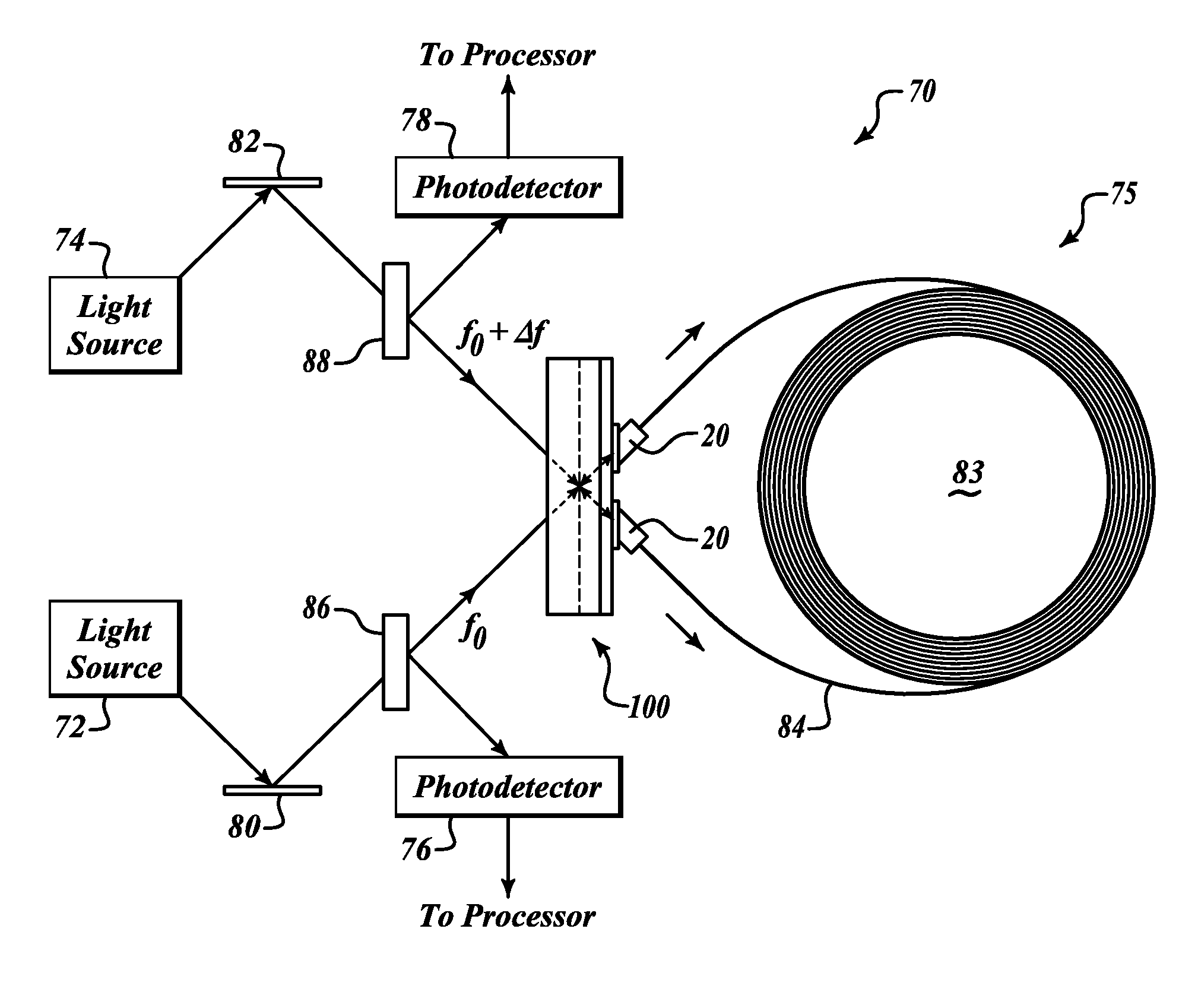
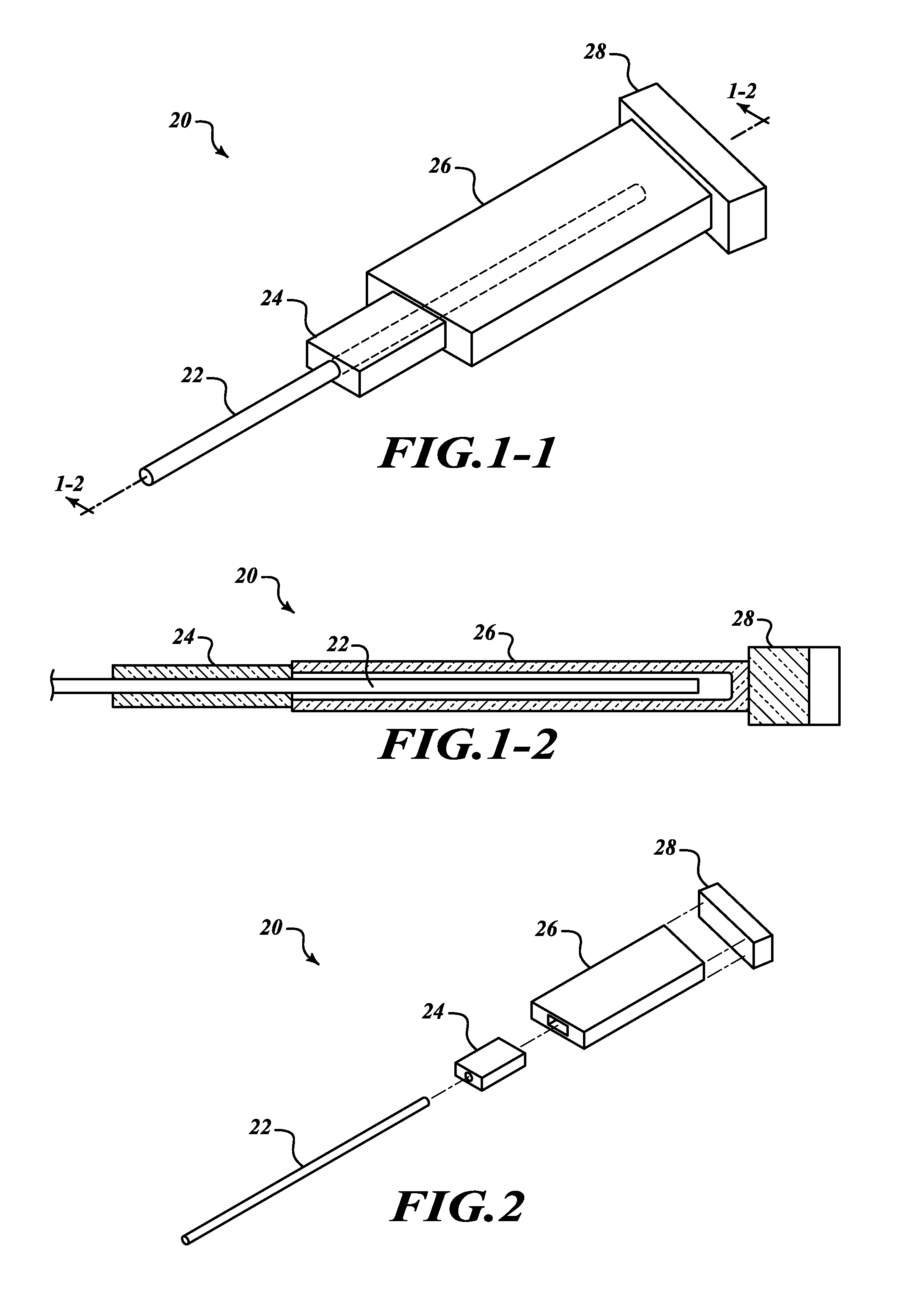
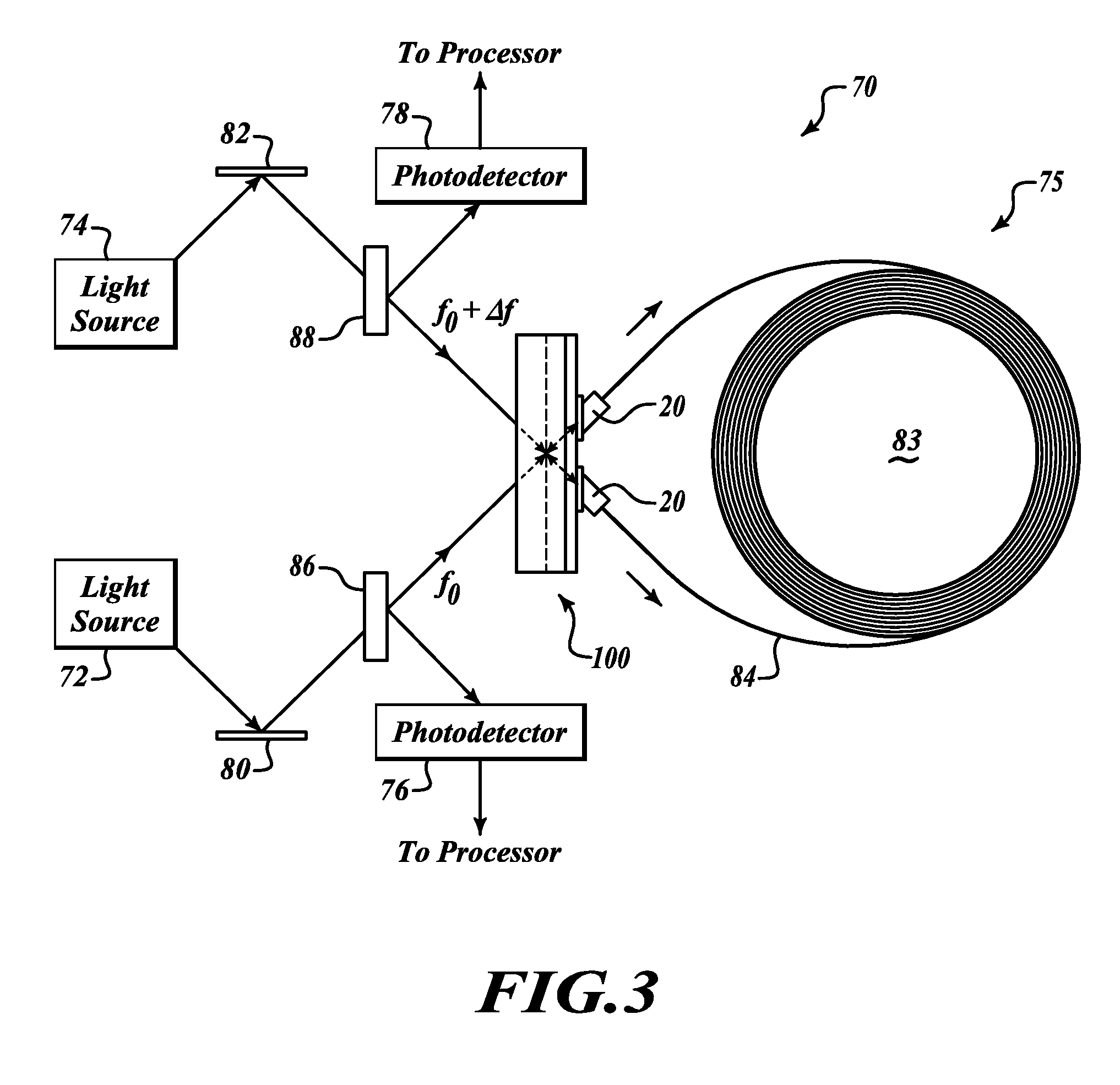
[0019]FIGS. 1-1, 1-2 and 2 illustrate various views of a coupling device 20 for attaching an end of a hollow core fiber 22 to optical components included in an interferometric fiber optic gyroscope (IFOG), a resonator fiber optic gyroscope (RFOG), or any other device that would benefit using hollow core fiber, and therefore benefit from reducing the effects that may result with an open-ended hollow core fiber 22.

[0020]The device 20 includes a glass ferrule 24, a sleeve 26, and a glass plate 28. The glass ferrule 24 may also be a glass capillary device. The glass ferrule 24 is attached to a first end of the sleeve 26. A second end of the sleeve 26 is attached to one side of the glass plate 28. Both the sleeve 26 and the ferrule 24 include a hollowed out cavity. The cavity within the sleeve 26 is quite a bit larger than the diameter of the hollow core fiber 22. The sleeve 26 and the ferrule 24 are molded or machined from glass. The ferrule 24, the sleeve 26 and the glass plate 28 are ...


PUM


Abstract

An optical coupling device for connecting hollow core optical fiber coils in a fiber optic gyro system. An example fiber optic gyro system includes a recirculator or an integrated optics chip, a fiber coil of hollow core optical fiber with first and second ends, and a coupling device that holds an end of the hollow core optical fiber in an enclosed cavity at some predefined distance from the recirculator or integrated optics chip. The coupling device includes a housing for rigidly holding the fiber end in position. The housing includes a cavity that receives the fiber end.

Description

BACKGROUND OF THE INVENTION[0001]Gyros have been used to measure rotation rates or changes in angular velocity about an axis of rotation. A basic conventional fiber optic gyro (FOG) includes a light source, a beam generating device, and a coil of optical fiber coupled to the beam generating device that encircles an area. The beam generating device transmits light beams into the coil that propagate in a clockwise (CW) direction and a counter-clockwise (CCW) direction along the core of the optical fiber. Many FOGs utilize glass-based optical fibers that conduct light along a solid glass core of the fiber. The two counter-propagating (e.g., CW and CCW) beams may experience different pathlengths while propagating around a rotating closed optical path, and the difference in the two pathlengths is proportional to the rotational rate.[0002]In a resonator fiber optic gyro (RFOG), the counter-propagating light beams are desirably monochromatic (e.g., in a single frequency) and circulate thro...

Claims


Application Information

Patent Timeline
Patent Type & Authority Patents(United States)
IPC IPC(8): G01C19/72
CPCG01C19/722G01C19/727G02B6/4207
Inventor SANDERS, GLEN A.KALISZEK, ANDREWDANG, THIEN
Owner HONEYWELL INT INC
Why Eureka
Try Eureka