X-ray system for irradiating material used in transfusions

a technology of irradiation equipment and transfusion facility, which is applied in the direction of x-ray tube targets, nuclear engineering, x-ray tubes, etc., can solve the problems of reducing the uniformity of irradiation equipment, and preventing the deployment of irradiation equipment at all transfusion facilities and other locations where blood transfusions are performed, etc. , to achieve the effect of reducing the need for large distances

Inactive Publication Date: 2010-04-27
APPLIED X RAD TECH
View PDF3 Cites 13 Cited by
  • Summary
  • Abstract
  • Description
  • Claims
  • Application Information

AI Technical Summary

Benefits of technology

[0004]Another key object of the invention is to provide a system with a greater uniformity of both the X-ray energy and it's intensity across the field of radiation and to reduce the necessity for large distances between the X-ray source and the material being irradiated. By reducing this distance, less shielding is required as the object / material being irradiated may be positioned close to the X-ray source, thereby reducing the volume that requires radiation shielding. Through “transmission geometry,” greater efficiency (nearly twice that obtained in “reflection geometry”) is achieved in converting electron beam energy into X-ray radiation.

Problems solved by technology

Although rare, TA-GVHD results in a mortality rate of greater than 90% of cases, when this complication occurs.
At this time there is no known, effective treatment for TA-GVHD.
However, cost and size of commercially available X-ray source irradiation equipment prevents deployment at all transfusion facilities and other locations where blood transfusions occur.

Method used


Image

  • X-ray system for irradiating material used in transfusions
  • X-ray system for irradiating material used in transfusions
  • X-ray system for irradiating material used in transfusions

Examples


Embodiment Construction

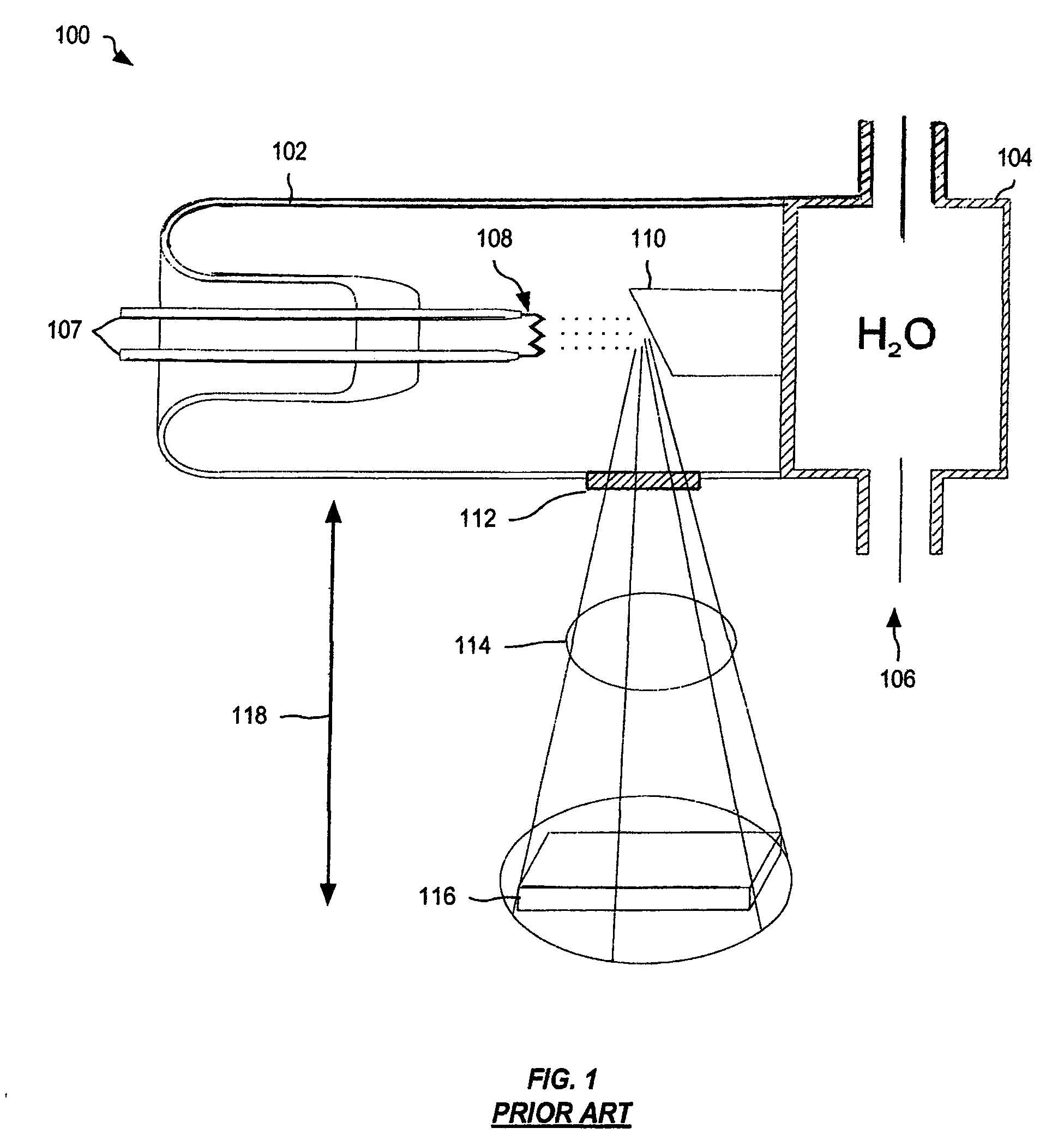
[0017]For the blood transfusion market, commercially available X-ray source blood irradiation equipment is based upon technology such as prior-art industrial, “reflective geometry” continuous emission X-ray source 100, shown in FIG. 1. X-ray source 100 consists of an evacuated enclosure 102 with a thermionic electron emission cathode filament 108, a reflective anode target 110, an X-ray window 112 and a cooling chamber 104.

[0018]Low voltage power is supplied to thermionic electron emission cathode filament 108 via electrodes 107. Current flowing through cathode filament 108, heats cathode filament 108, resulting in thermionic emission of electrons. High voltage applied between cathode filament 108 and reflective anode target 110 creates a high magnitude electric field between these two components of X-ray source 100. Thermally emitted electrons from cathode filament 108 are accelerated by the high magnitude electric field toward reflective anode 110. These electrons are focused on a...


PUM


Abstract

A system for irradiating material used in transfusions. The material can be pre-transfused blood, blood components and marrow. The system includes a vacuum chamber with a plate cathode inside. The cathode has a large beam electrode field-electron emissive surface with a selected cross-sectional shaped area. A power supply is connected to the cathode for generating negative high-voltage pulses and causing a selected cross-sectional shaped beam of electrons to be emitted. An electron window is also disposed inside the vacuum chamber and made of thin metal foil. The electron window receives the selected cross-sectional shaped beam of electrons therethrough and onto an electron target disposed outside the vacuum chamber. The electron target receives the selected cross-sectional shaped beam of electrons thereon and generates a selected cross-sectional shaped X-ray beam. A cathode filter is disposed next to the electron target and eliminates low energy beams from the spectrum of the X-ray beam. The filtered X-ray beam exposes the material to high energy beams for irradiation.

Description

[0001]This non-provisional patent application claims the benefit of an earlier filed provisional patent application Ser. No. 61 / 013,939, by the subject inventors, and filed on Dec. 14, 2007.BACKGROUND OF THE INVENTION[0002]In transfusion and transplant medicine, the transfusion of blood or blood components sometimes results in TA-GVHD (Transfusion Associated-Graft-Versus-Host Disease). Although rare, TA-GVHD results in a mortality rate of greater than 90% of cases, when this complication occurs. At this time there is no known, effective treatment for TA-GVHD. Without available treatment, the only method of dealing with TA-GVHD is prevention. Today, the only accepted method of prevention for TA-GVHD is in the FDA prescribed dose of ionizing radiation, provided by either gamma emitting radioactive sources or by X-ray sources, applied to pre-transfused, blood and blood components in transfusion medicine. However, cost and size of commercially available X-ray source irradiation equipmen...

Claims


Application Information

Patent Timeline
Patent Type & Authority Patents(United States)
IPC IPC(8): H01J35/00
CPCG21K1/10G21K5/08G21K5/10H01J35/065H01J35/12H01J35/18H01J2235/186H01J2235/083H01J2235/087H01J2235/1204H01J2235/1295H01J2235/163H01J2235/18H01J2235/062H01J35/116H01J35/13H01J35/186
Inventor WOODRUFF, RALPH R.TOSHKOV, STOYAN A.DONCHEV, TODOR I.
Owner APPLIED X RAD TECH
Why Eureka
Try Eureka