Hydrogen G-cycle rotary internal combustion engine

a rotary internal combustion engine and rotary technology, applied in the direction of machines/engines, rotary/oscillating piston pump components, liquid fuel engines, etc., can solve the problems of increasing inflation and geopolitical tension, reducing the efficiency of combustion engines, etc., to achieve high tensile strength, low friction and wear, and high vane belt motion

Active Publication Date: 2010-05-04
PRIME MOVER INT
View PDF15 Cites 34 Cited by
  • Summary
  • Abstract
  • Description
  • Claims
  • Application Information

AI Technical Summary

Benefits of technology

[0085]The vane and seal anti-centrifugal system of the present invention uses a series of belts that are connected to a toggling system attached to the bottom of each of the vanes. Two series of belts are formed where the two belts are split between alternating vanes. One belt runs along the radial center of the engine and around the driveshaft and the other belt is spit in half and runs on the outside of the center belt. Each of the outer belts is one half the width of the center belt. The operation of the belt system works similarly to the string / finger cat's cradle game where players use a string loop to make creative string shapes by distorting the loop with their fingers. To keep the creative string shape, the players must use both hands and pull them apart to apply tension on the string. The players can change sting shape or position by adjusting the string with their fingers, but must maintain a constant tension to the string with all fingers. The present invention operates in a similar way. In an eight vane engine system, four alternating vanes are connected to the center belt system, and four vanes are connected to the outer belt system. In each belt system, as two vanes follow the inner housing stator profile and begin to extend from the rotor's center they pull the other two vanes back into the rotor. This system also operates much like the rhombic linkage system by balancing the centrifugal vane and seal forces with centripetal forces of the other vanes and seals. The advantage of the present invention is that it also uses a vane belt toggling system and profile belt that allows the vanes and seals to follow asymmetrical inner housing profiles where the combustion / expansion is greater than 90 degrees CA from TDC. The toggles allow the vane segments to be extended or shortened to adjust to the inner housing profile distortions. A profile belting system is a third belting system comprised of two smaller belts that go on the outside perimeter of the two inner belting systems. The profile belting system connects both the center and outer belting system together as a unified system and acts like a dynamic cam channel to help keep the vanes and seals in proper position with the inner housing stator surface as they rotate around an asymmetrical or distorted oval inner housing stator profile. Another advantage of the proposed invention is that each of the vane toggle systems is connected to an adjustable tension bar that can adjust the belt tension from any system wear or belt stretching.
[0086]By using an active cooling system to spray water into the rotor center the temperature around the belting system can be maintained at around 100 degrees C. or 212 degrees F. At this temperature, a wide variety of different materials can be used as belting material. These materials include woven Nextel 610 and AGY's 933-S2 glass, fiberglass, carbon fibers, or stainless steel wire. The preferred belting material is high tensile strength fibers that are woven into flat belt segments and connected to the vane toggles. The vane belts will ride over belt arches located in between two connected vanes. The belt arches will contain roller bearings to further assist the movement of the belts across the vane arches. The roller bearings are also connected to a spring system that compresses at high rpm speeds greater than 1,000 rpm. At these speeds, the roller bearings break contact with the vane belts and the belts slide across small rounded surfaces of the belt arch that have been coated with a solid lubricant. The solid lubricant allows very high vane belt motion across the belt arch with very low friction and wear. The belts themselves can also be coated with a solid lubricant to further reduce friction and wear.Rotor Structure
[0087]It is a further object of the present invention to provide an improved rotor structure that is lighter and stronger than other rotor systems.
[0088]The engine rotor is made up of eight or six segments depending on the size and engine configuration. The driveshaft preferably is octagon or hexagon in shape to match eight or six rotor segments, respectively. The bottom of each of the rotor segments preferably rests on one of the flat surfaces of the driveshaft. Round lock plates slide over each of the ends of the driveshaft and lock all the different rotor segments together to form a single rotor. The rotor preferably has a top semi-circular shape that matches the inner housing profile. The rotor top is connected to two side plates that make the rotor into an upside down U-shape like the vane and from a large open space under the rotor surface. The top semi-circular shape acts like a strong arch and provides great strength to the rotor and allows the large open space underneath. This reduces the weight of the engine and the material cost of manufacturing the rotor. It also provides space for the operation of the vane anti-centrifugal belting system to operate.Combustion Cavity Vortex Turbulence
[0089]The combustion cavity forms a crescent shape and is narrower than typical combustion chambers. Hydrogen has a much higher flame speed than gasoline and diesel fuels. This generates surface shear with the chamber gases and water with the outer housing surface to generate mixing turbulence to improve flame front propagation throughout the entire chamber. With a high inner housing surface temperature the sear turbulence across this heated surface will further accelerate combustion and flame front propagation.
[0090]The combustion recess is primarily to slightly stratify the hydrogen and water. This helps provide a slight hydrogen homogeneous combustion section separate from the water that will be on the sides and back. The curvature of the combustion recess also helps generate chamber turbulence to improve hydrogen combustion and then mixing with water.

Problems solved by technology

The growing demand for oil from various nations around the world is resulting in higher energy prices that have the potential to increase inflation and geopolitical tensions between the nations competing for the same limited oil reserves.
Even if the supply of oil could be increased to meet the demand, doing so has the further potential of producing higher CO2 emissions with the possibility of more rapid global warming.
However, fuel cell durability, efficiency, fuel purity requirements, hydrogen storage, and cost limitations are major implementation barriers.
It is unclear, however, whether hybrid electrical propulsions systems provide high enough value added efficiency benefits to consumers to justify their higher cost.
Converting existing internal combustion engine systems to operate on hydrogen is also not without problems.
The combustion temperature for hydrogen is much higher than for gasoline, resulting in high amounts of NOx emissions being formed.
Using lean hydrogen fuel mixtures to reduce potential NOx emissions, but also greatly reduces the power output performance levels.
Direct hydrogen injection can improve this problem, but the injectors are very expensive and require high pressures and tolerances.
The injection pulse provides limited amount of hydrogen fuel making it insufficient for larger power applications.
The dryness of the hydrogen gas also makes it more difficult for the pulsing injectors to work and increases injector wear.
Moreover, the high diffusiveness of hydrogen gas often results in the hydrogen gas passing through engine sealing systems into crank shaft regions, resulting in very undesirable combustion that can damage the engine and / or ignite the oil lubricant.

Method used


Image

  • Hydrogen G-cycle rotary internal combustion engine
  • Hydrogen G-cycle rotary internal combustion engine
  • Hydrogen G-cycle rotary internal combustion engine

Examples


Embodiment Construction

Engine Operation Overview

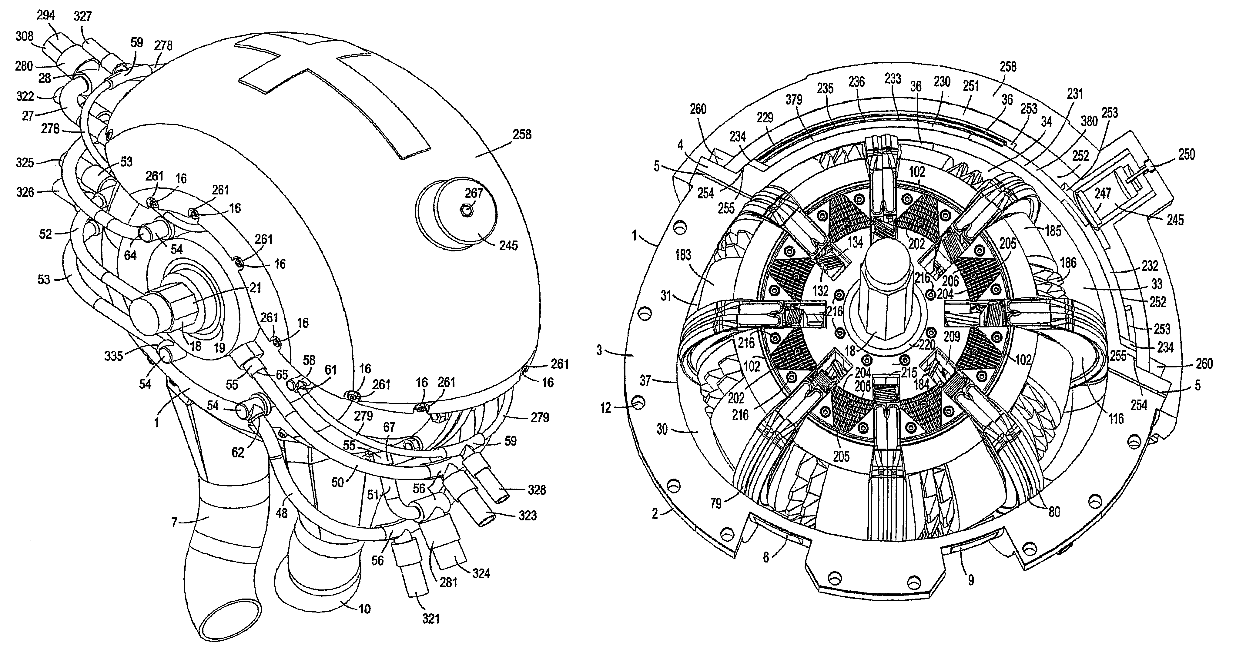
[0162]The G-cycle engine 1 includes an outer housing 2 having an inner housing surface 37 in the form of a distorted oval within which a rotor assembly 183 rotates clockwise. See FIGS. 3 and 4. The housing 2 includes a sodium vapor chamber 229 separate from and not in communication with the compression, combustion and expansion zones 31, 32 and 33, respectively of the engine 1. Thus the inside surface 37 of housing 2 slopes arcuately inwardly toward a driveshaft 18 about which the rotor 183 rotates from an intake port 6 at about 0° crank angle through about 105° to a circumferential location adjacent the beginning of the sodium vapor chamber229. The inner surface 37 of the housing 2 adjacent to the beginning of the sodium vapor chamber 229 and the beginning of the expansion zone 33 arcuately moves outwardly away from the driveshaft 18 to obtain a maximum geometric distance from the center of driveshaft 18 at about 147° beyond the beginning of the expansion z...


PUM


Abstract

A hydrogen G-cycle rotary vane internal combustion engine has a sodium vapor chamber transferring excess combustion heat into combustion chambers. An active water cooling system captures heat from the engine housing stator, rotor, and sliding vanes and transfers it back into the combustion cycle by premixing it with hydrogen to reduce peak combustion temperature and with an early an late stage combustion chamber injection to help transfer heat from the sodium vapor chamber, to control chamber temperature, and to increase chamber vapor pressure. A combustion chamber sealing system includes axial seals between the rotor and the stator, vane face seals, and toggling split vane seals between the outer perimeters of the sliding vanes and the stator. Sliding vanes reciprocate laterally in and out of the rotor assisted by a vane belting system. A thermal barrier coating minimizes heat transfer and thermal deformation. Solid lubricants provide high temperature lubrication and durability.

Description

[0001]This application claims the benefit of U.S. Provisional Application Ser. No. 60 / 721,521, filed Sep. 29, 2005, the entire contents of which are incorporated herein by reference.[0002]This invention relates to internal combustion engines, and more specifically to rotary vane engines using a hydrogen fuel thermodynamic G-cycle.BACKGROUND OF THE INVENTION[0003]The growing demand for oil from various nations around the world is resulting in higher energy prices that have the potential to increase inflation and geopolitical tensions between the nations competing for the same limited oil reserves. Even if the supply of oil could be increased to meet the demand, doing so has the further potential of producing higher CO2 emissions with the possibility of more rapid global warming.[0004]Currently many transportation, oil, and energy companies and governments are investing billions of dollars in hydrogen related research and development programs to produce a fuel source that will gradual...

Claims


Application Information

Patent Timeline
Patent Type & Authority Patents(United States)
IPC IPC(8): F02B53/00F01C1/00F01C19/00F01C21/04F04C29/04F04C27/00F04C2/00F04C18/00F04C15/00F02M25/00F02B53/04F01C21/06F01P9/02F01P9/04F02B47/02
CPCF01C1/3446F01C21/06Y02T10/166Y02T10/12F02B53/00F01C1/00F02B53/04F01C19/00
Inventor GUTHRIE, BARRY R.
Owner PRIME MOVER INT
Why Eureka
Try Eureka