
Connection arrangement and method for optical communications

Inactive Publication Date: 2010-05-04
AVAGO TECH WIRELESS IP SINGAPORE PTE
View PDF11 Cites 3 Cited by
  • Summary
  • Abstract
  • Description
  • Claims
  • Application Information

AI Technical Summary

Benefits of technology

[0023]In brief, the arrangement described herein makes an ESA pluggable into the OSA of an electro-optical communication device such as a transceiver or vice-versa. This solution offers a significantly shorter RF path compared to fixed leads or a conventional flex arrangement. This avoids also the problems of rigid connections of the OSA and ESA, improving shock and vibration resistance. Additionally, the capability for quick and simple connection and / or reconnection improves the testing environment of the OSA and ESA. In the case of malfunctioning, only the malfunctioning portion is removed and replaced.

Problems solved by technology

Proper and effective connection between the OSA and the ESA is a critical issue in manufacturing optical transceivers, especially when operating rates of the order of 10 Gbit / s and higher are contemplated.
Assembling the OSA and the ESA is usually performed manually or by resorting to automated, dedicated soldering process that inevitably tend to be quite expensive.
However effective, the prior art solutions discussed in the foregoing are costly and entail a number of disadvantages.
This requires design efforts, expensive profiling fixtures and making the leads longer than strictly required for connection purposes.
However, longer leads included in the RF portion of the transceiver militate against high data throughput.
Unfortunately, using a flex renders the assembly process rather complicated, this being particularly the case if an automated production environment is considered.
In the case of malfunctioning of either subassembly, the transceiver as a whole is usually disposed of: in fact, separating the malfunctioning subassembly from the subassembly that operates correctly, removing the malfunctioning subassembly from the transceiver, substituting a replacement unit for the malfunctioning subassembly removed and re-establishing the mechanical and electrical connections between the OSA and the ESA is an expensive and time-consuming process, and may also give rise to problems in terms of reliability.
In turn, the OSA and ESA are both rather expensive components, and dispensing with transceiver—as a whole—because only one of the ESA and the OSA is malfunctioning is hardly an acceptable choice from the economical viewpoint.

Method used


Image

  • Connection arrangement and method for optical communications
  • Connection arrangement and method for optical communications
  • Connection arrangement and method for optical communications

Examples


Embodiment Construction

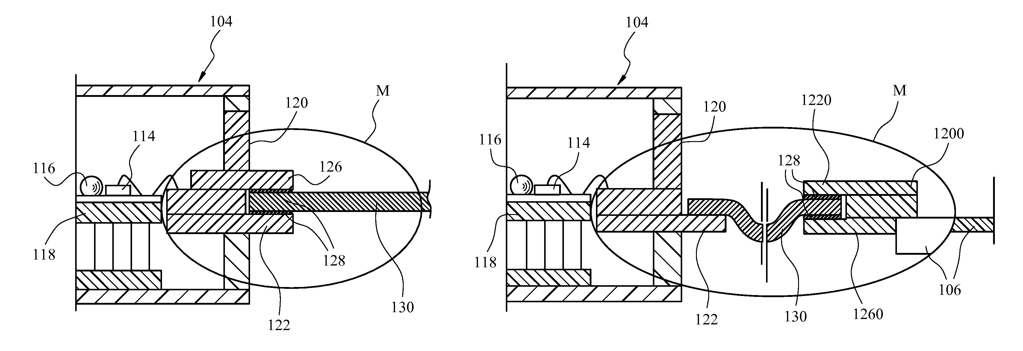
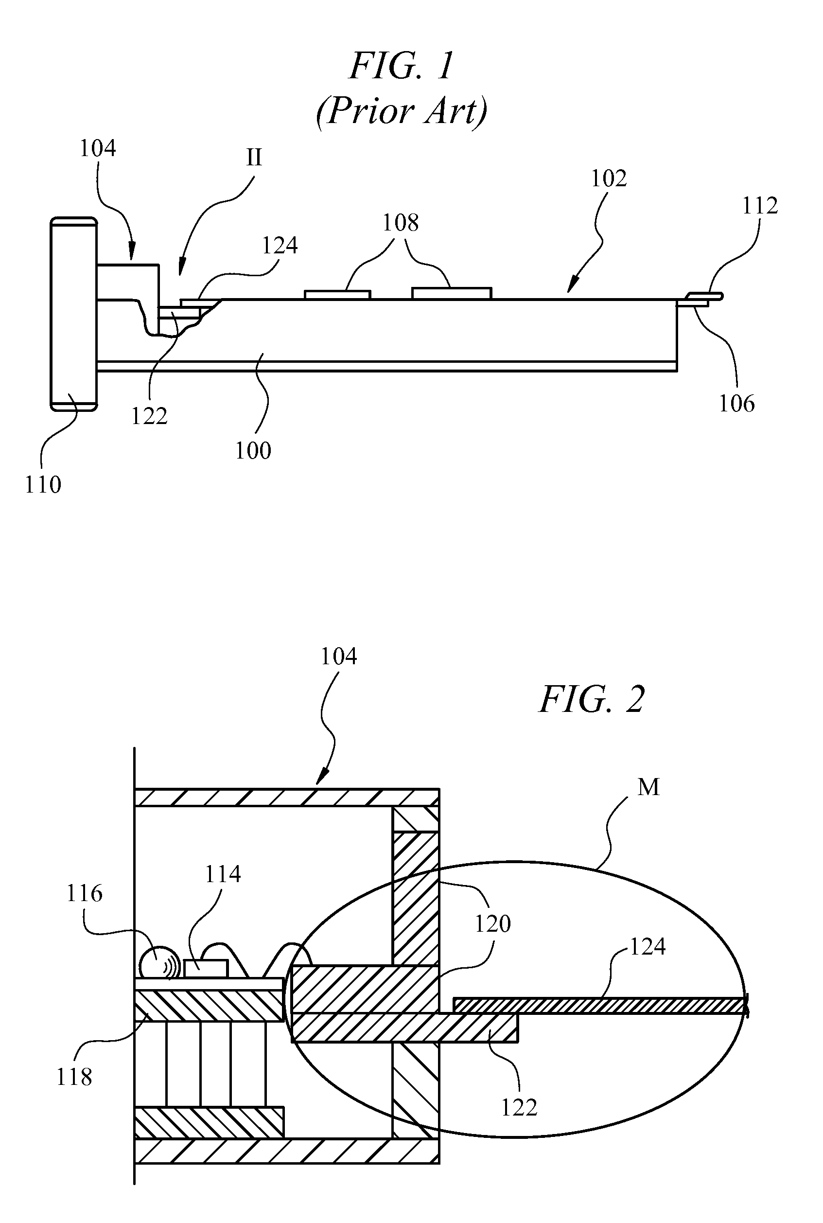
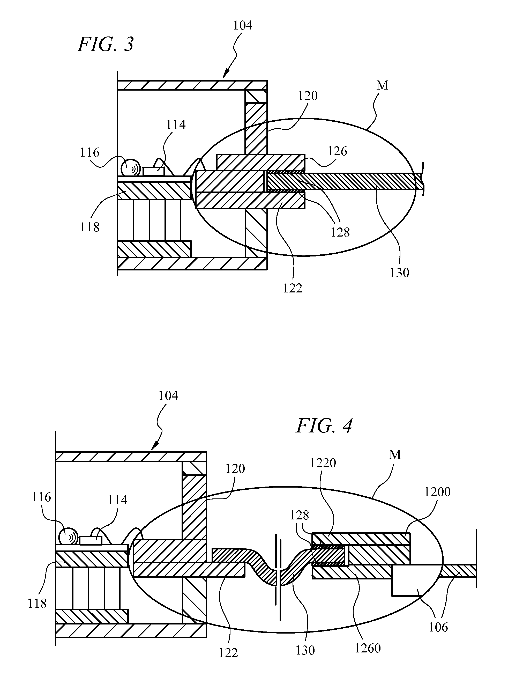
[0029]In FIGS. 3 and 4, reference signs / numerals identical to those already appearing in FIG. 1 and FIG. 2 were used to designate parts / elements that are identical or equivalent to those already described in connection with FIGS. 1 and 2.

[0030]Consequently, FIGS. 3 and 4 again show a feedthrough 120 comprised of e.g. a ceramics material such as alumina as required for high data rate operation (10 Gbit / s or higher).

[0031]The feedthrough 120 of FIG. 4 (to be described later) is essentially identical to the feedthrough 120 of FIG. 2.

[0032]Conversely, the layout of the feedthrough 120 of FIG. 3 uses the feedthrough 120 of FIG. 2 as a basis to include therein a further pod-like extension 126 that jointly defines with the pod-like formation portion 122 a clamp or socket. A “flex” circuit 130 as described in the foregoing can thus be plugged into that clamp or socket and reliably retained therein to ensure electrical connection between the ESA and the OSA, while making possible for it to b...


PUM


Abstract

An arrangement for connecting an electronic subassembly and an optical subassembly in an electro-optical communication device such as an electro-optical transceiver. The arrangement includes a body of a rigid dielectric material for mounting e.g. on the optical subassembly. The body has electrically conductive pathways provided thereon and includes a shaped portion providing a socket-like formation. At least one electrical contact element is coupled with e.g. the electronic subassembly. The electrical contact element is pluggable into the socket-like formation of the body of rigid dielectric material and includes an elastic device adapted to elastically co-operate with the socket-like formation of the body of rigid dielectric material to retain the electrical contact element plugged in the socket-like formation to provide electrical contact with the electrically conductive pathways provide thereon, while permitting vibrational displacement of the electrical contact element within the socket-like formation.

Description

BACKGROUND[0001]1. Field of the Disclosure[0002]The present disclosure relates to connection arrangements for optical communications.[0003]The disclosure was developed with specific attention paid to the possible use in connecting Optical Sub Assemblies (OSA's) and Electronic Sub Assemblies (ESA's) in optical communication devices such as e.g. transceivers for optical communications.[0004]2. Discussion of the Background Art[0005]Electro-optical communication devices such as transceivers for optical communications typically comprise an Electronic Sub Assembly (ESA) and an Optical Sub Assembly (OSA) in a single package. Such an arrangement is schematically illustrated in FIG. 1, where a carrier body 100, typically of a metal material, is shown having mounted thereon an Electronic Sub Assembly (ESA) 102 and an Optical Sub Assembly (OSA) 104. The Electronic Sub Assembly 102 is e.g. in the form of a small printed circuit board (PCB) 106 having electronic circuitry 108 mounted thereon. Th...

Claims


Application Information

Patent Timeline
IPC IPC(8): H01R12/00H01R12/79H04B10/40H04B10/80
CPCG02B6/4201H01R12/62H04B10/40H05K3/365H04B10/801H05K2201/0919H05K1/0306H05K2201/09163G02B6/4283G02B6/4274G02B6/4281G02B6/4284H01R12/00
Inventor GUJA, VICTOR BOGDANCERISOLA, MAUROCAMPI, DOMENICO
Owner AVAGO TECH WIRELESS IP SINGAPORE PTE
Learn More