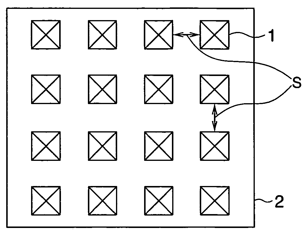
Lens array sheet

a technology of array sheets and lenses, applied in the field of array sheets, can solve the problems of reducing luminance drastically when out of the light condensing range, sacrificing other performance, etc., and achieve the effect of wide viewing angle and improving light condensing efficiency

Inactive Publication Date: 2010-05-04
ZEON CORP
View PDF28 Cites 4 Cited by
  • Summary
  • Abstract
  • Description
  • Claims
  • Application Information

AI Technical Summary

Benefits of technology

[0008]An object of the present invention is to provide a lens array sheet having a wide viewing angle and an improved light condensing efficiency, a mold suitable for being used for producing the lens array sheet, a light condensing plate comprising the lens array sheet, an organic electroluminescence element comprising the lens array sheet, and a display device comprising the element.

Problems solved by technology

When improving one of these characteristics, it is liable that other performance has to be more or less sacrificed and it has been very difficult to improve all performances at a time.
This method uses a light condensing effect of a prism and is capable of attaining high luminance without increasing an electric power and a thickness of the device, while it has a disadvantage that the luminance drastically declines when being out of the light condensing range.
However, light transmittance of a liquid crystal panel is too low to use it as a backlight of a liquid crystal display device, therefore, the light condensing efficiency has to be furthermore improved comparing with that in a conventional backlight using a cold-cathode tube, etc.
However, when using a prism lens having a line shaped surface, which has been conventionally used as a light condensing plate of a liquid crystal substrate, as a light condensing plate of an organic electroluminescence element, there is a disadvantage that the viewing angle becomes narrow.

Method used


Image

  • Lens array sheet
  • Lens array sheet
  • Lens array sheet

Examples


example 1

[0061]Production of Substrate

[0062]After applying a positive type photoresist composition (product name: ZPP1700PG) made by ZEON Corporation by spin-coating on a substrate obtained by forming a film of SiO2 to 300 Å on a silicon, the result was prebaked at 100° C. to obtain a resist film of 1.5 μm on the substrate.

[0063]The obtained resist film was subjected to exposure of 50 mJ / cm2 by an exposure apparatus “PLA501F” made by Canon Inc. via a mask, development processing was performed by a 2.38% tetramethyl ammonium hydroxide solution for 60 seconds, and then, rinse processing by ultrapure water was performed for 30 seconds. The substrate was dried by spin processing and prebaking processing at 120° C. was finally performed to obtain a resist pattern on the substrate.

[0064]The thus obtained substrate was dipped in a hydrofluoric acid buffer solution (mixture of 3.6% hydrofluoric hydrofluoric water and 18% hydrofluoric ammonium water by 1:1 (in volume) at 20° C. It will be the same be...

example 2

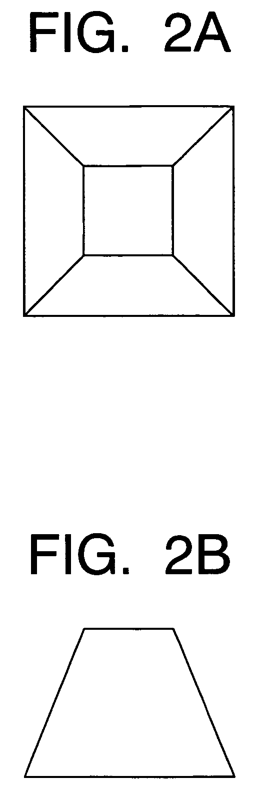
[0081]The mold in the example 1 was used. The mold was immersed in a potassium bichromate solution (0.1 wt %) for 30 seconds and mold releasing processing was performed by oxidizing the mold surface, then, a nickel layer (metal layer) was stacked under the same condition as that in the example 1 and the stacked nickel layer was peeled from the mold, so that a mold (concave mold) formed with pyramid-shaped “recesses” having a base angle of side surfaces of approximately 55° and a height of 14 μm in a hound's-tooth check shape was obtained.

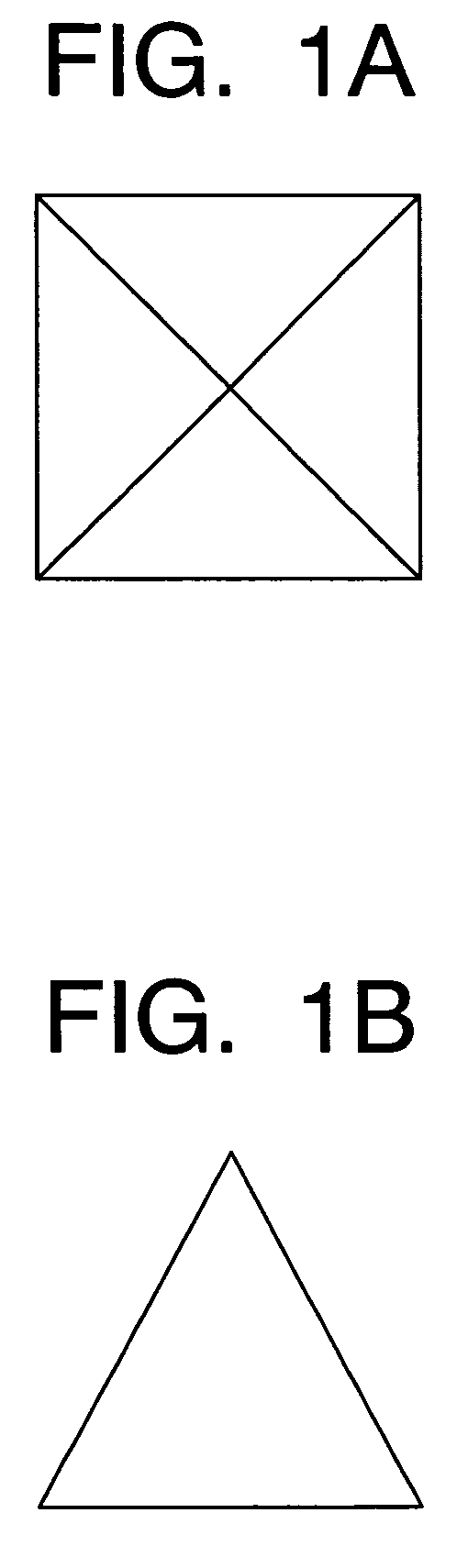
[0082]By using the obtained mold, a lens array sheet was produced in the same way as in the example 1. The obtained lens array sheet was formed on its surface with pyramid-shaped “projections” having a bottom surface of 20 μm×20 μm, a base angle of side surfaces of approximately 55° and a height of 14 μm in a hound's-tooth check shape.

[0083]By using the lens array sheet, an organic electroluminescence element was produced, and the luminance was meas...


PUM


Abstract

A lens array sheet having a plurality of pyramid-shaped projections or recesses on a surface of its transparent base material film, particularly suitable to be used as a light condensing plate of an organic electroluminescence element is provided.

Description

FIELD OF THE INVENTION[0001]The present invention relates to a lens array sheet suitable to a light condensing plate used for a display device of an organic electroluminescence element and liquid crystal, etc., a mold suitable for being used for producing the lens array sheet, a light condensing plate composed of the lens array sheet, an organic electroluminescence illuminant comprising the lens array sheet, and a display device comprising the illuminant.BACKGROUND ART[0002]There are demands for a surface lighting device used for a display device to have many characteristics, such as high luminance, low power consumption and thin shape. When improving one of these characteristics, it is liable that other performance has to be more or less sacrificed and it has been very difficult to improve all performances at a time.[0003]To overcome the plurality of challenges, a sheet (lens array sheet) having a lens array formed with a fine concave and convex pattern, such as a prism shape and a...

Claims


Application Information

Patent Timeline
Patent Type & Authority Patents(United States)
IPC IPC(8): H05B33/22G02B3/00G02B5/02H01L51/52
CPCG02B3/0031G02B3/0043G02B3/0056G02B5/021H05B33/22G02B5/0268G02B5/0231G02B5/045H01L51/5275H10K50/858G02B1/041
Inventor KASHIWAGI, MOTOFUMIKUSANO, KENJI
Owner ZEON CORP
Why Eureka
Try Eureka