
Heat-assisted magnetic recording head and method of manufacturing the same

a magnetic recording and heating technology, applied in data recording, instruments, cabinets, etc., can solve the problems of difficult to record information in a magnetic recording medium with a relatively high coercive force, and achieve the effect of high density recording and small siz

Inactive Publication Date: 2010-05-04
SAMSUNG ELECTRONICS CO LTD
View PDF17 Cites 34 Cited by
  • Summary
  • Abstract
  • Description
  • Claims
  • Application Information

AI Technical Summary

Benefits of technology

The present invention provides a heat-assisted magnetic recording head that can achieve high-density recording by creating a small light spot and integrating it with a waveguide. The head includes a magnetic recording pole and a return pole to form a magnetic path. A light source emits light, which is guided through a photonic crystal waveguide to the recording medium. A nano aperture enhances the optical field by varying the intensity distribution of the light. The head can be fabricated integrally with the waveguide. The invention also provides a method of manufacturing the heat-assisted magnetic recording head. The technical effects include improved recording performance and higher data storage capacity.

Problems solved by technology

Previously, it has been difficult to achieve a recording density above 500 Gb / in2 using a conventional magnetic recording method.
Since reduction of the grain size increases thermal instability of a recorded bit, a medium having a relatively high coercive force is necessary.
Since a magnetic field generated by a magnetic recording head and applied to a magnetic recording medium has a limited intensity, it is difficult to record information in a magnetic recording medium when the magnetic recording medium is formed of a material having a relatively high coercive force for providing good thermal stability.
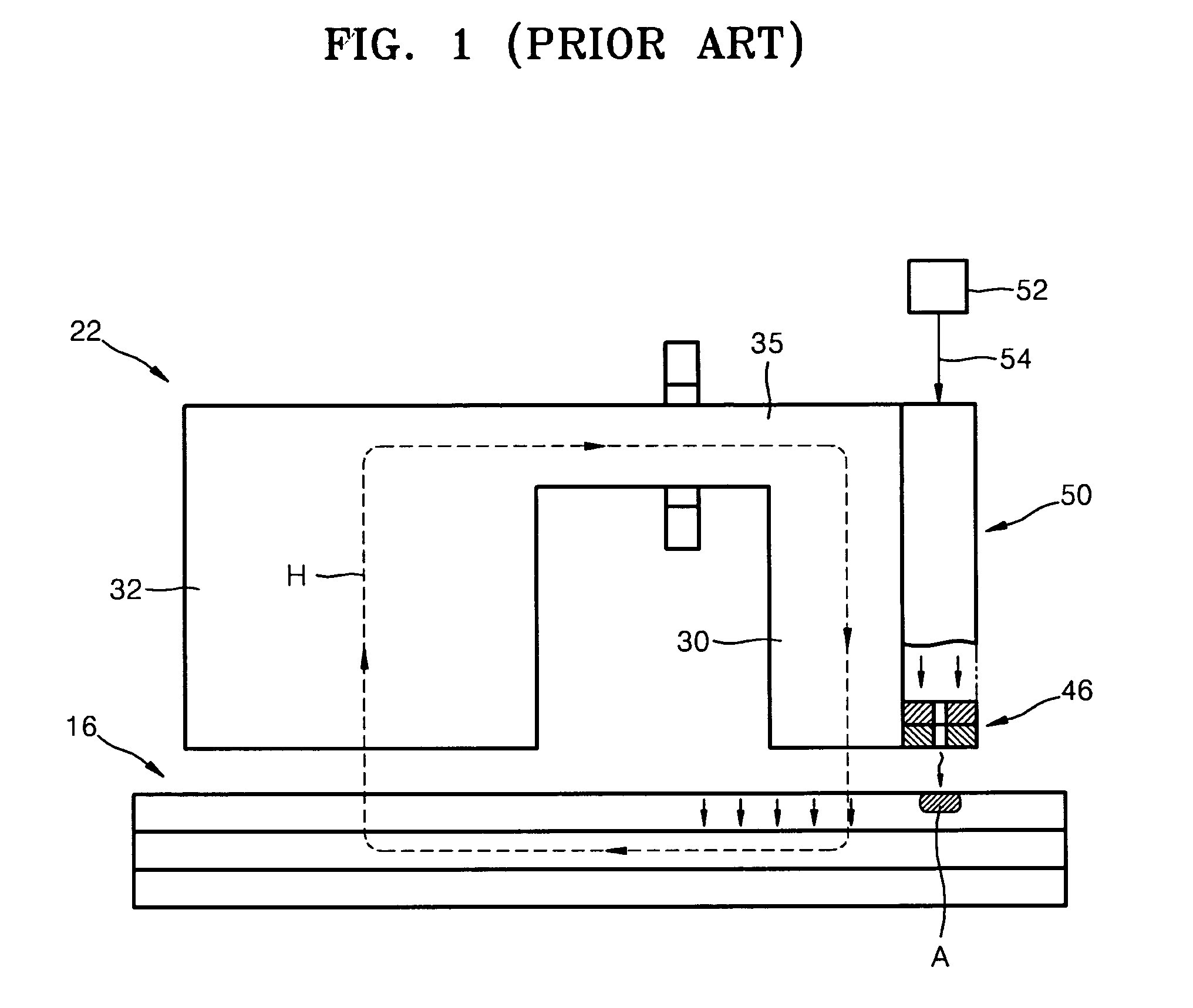
Therefore, the installation position of the light source is limited.
The limitation of the installation position of the light source reduces overall design flexibility of the HAMR head as well as an actual manufacturing flexibility.
In addition, since the EM radiation emission structure 46 is separately prepared and attached to an extreme end of the waveguide 50, it is difficult to manufacture the HAMR head through a semiconductor wafer fabrication process.

Method used


Image

  • Heat-assisted magnetic recording head and method of manufacturing the same
  • Heat-assisted magnetic recording head and method of manufacturing the same
  • Heat-assisted magnetic recording head and method of manufacturing the same

Examples


Embodiment Construction

[0049]The present invention will now be described more fully with reference to the accompanying drawings, in which exemplary embodiments of the invention are shown.

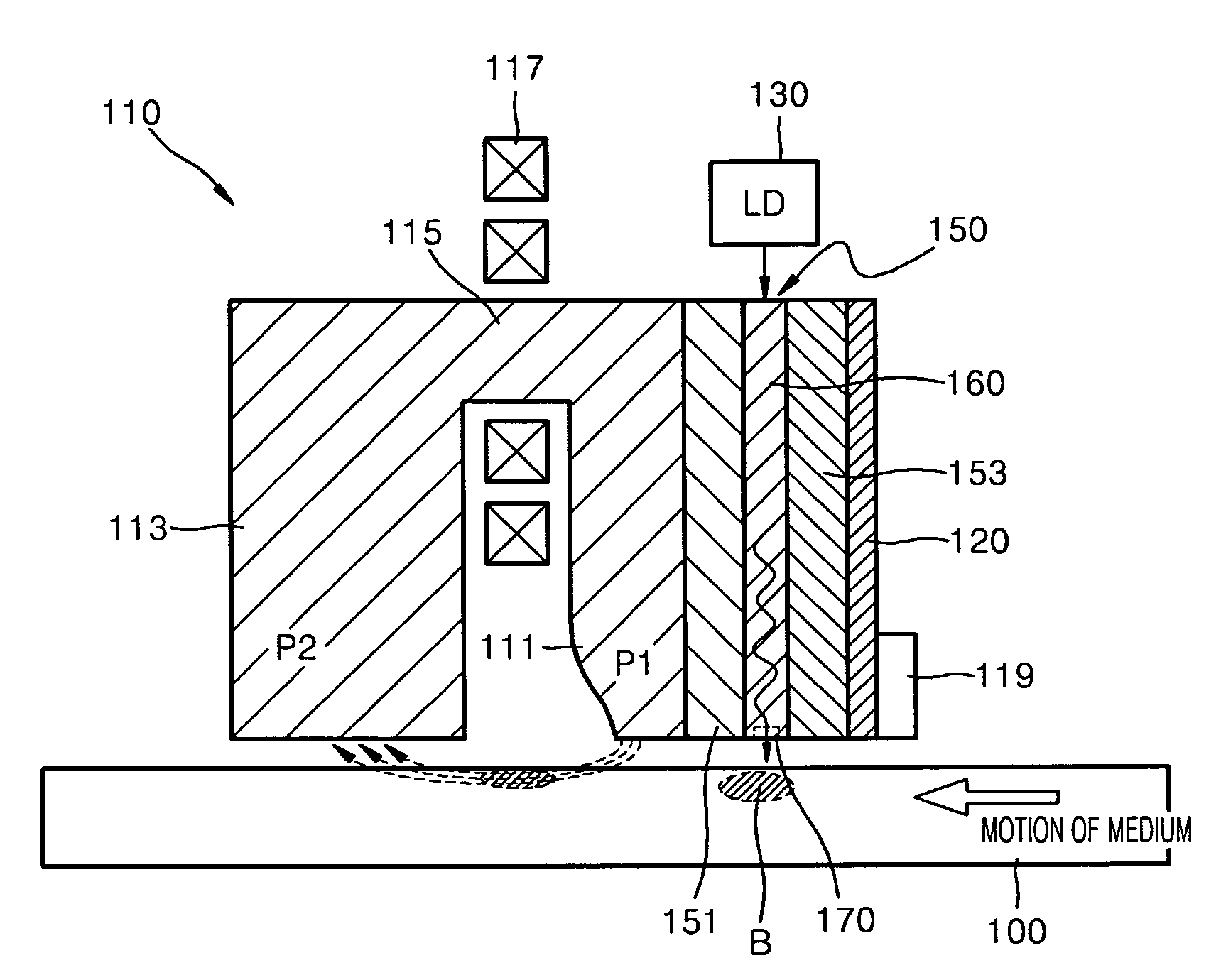
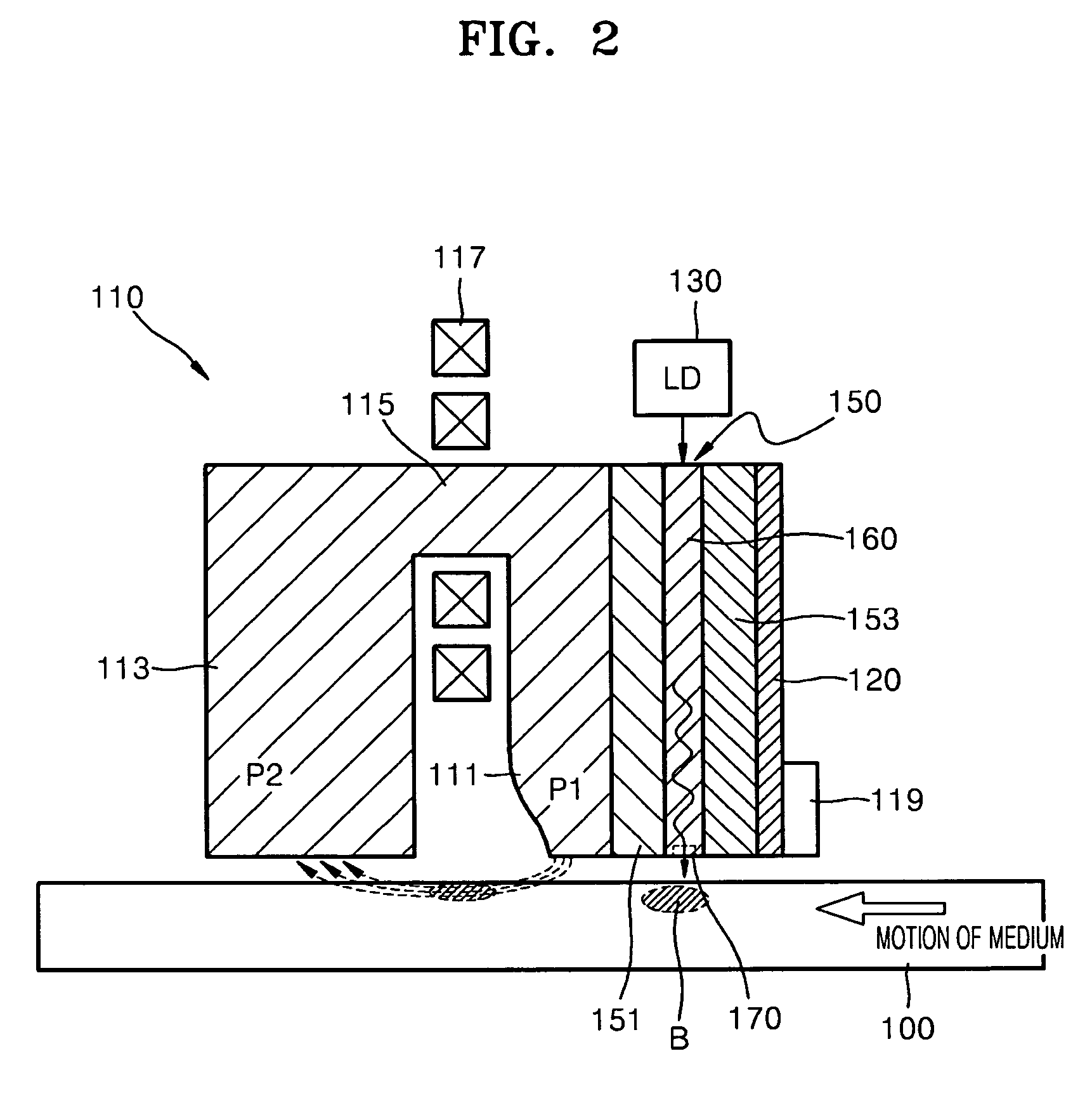
[0050]FIG. 2 is a schematic view of a HAMR head according to an exemplary embodiment of the present invention and FIG. 3 is a schematic view of a HAMR head according to another exemplary embodiment of the present invention.

[0051]Referring to FIGS. 2 and 3, the HAMR head includes a magnetic recording head 110, a light source 130 which emits light, and an optical transmission module 150 disposed at a side of the magnetic recording head 110 to transmit the light emitted from the light source 130. The optical transmission module 150 transmits the light emitted from the light source 130 to a portion B of a magnetic recording medium 100 to locally heat the portion of the magnetic recording medium 100 and thus temporarily reduce a coercive force of the portion B of the magnetic recording medium 100, thereby expediting recording....


PUM

PropertyMeasurementUnit
magneticaaaaaaaaaa
optical fieldaaaaaaaaaa
recording densityaaaaaaaaaa

Abstract

A heat-assisted magnetic recording head (HAMR) head includes a magnetic recording head including a recording pole for applying a magnetic recording field on a magnetic recording medium and a return pole magnetically connected to the recording pole to form a magnetic path, a light source for emitting light, and an optical transmission module including an photonic crystal waveguide disposed at a side of the magnetic recording head to guide light incident from the light source and a nano aperture for enhancing an optical field by varying an intensity distribution of the light guided through the photonic crystal waveguide.

Description

CROSS-REFERENCE TO RELATED PATENT APPLICATIONS[0001]This application claims priority from Korean Patent Application No. 10-2006-0003113, filed on Jan. 11, 2006, in the Korean Intellectual Property Office, the disclosure of which is incorporated herein in its entirety by reference.BACKGROUND OF THE INVENTION[0002]1. Field of the Invention[0003]The present invention relates to a heat-assisted magnetic recording head and a method of manufacturing the same and, more particularly, to a heat-assisted magnetic recording head with which an optical transmission module can be easily integrated and which can easily be changed to have an optical path in a desired direction and a method of manufacturing the same.[0004]2. Description of the Related Art[0005]Previously, it has been difficult to achieve a recording density above 500 Gb / in2 using a conventional magnetic recording method.[0006]In the field of magnetic information recording, many studies have been performed to overcome magnetic record...

Claims


Application Information

Patent Timeline
Patent Type & Authority Patents(United States)
IPC IPC(8): G11B5/127
CPCG11B5/02G11B5/127G11B5/314G11B2005/0021G11B2005/001A47B77/00
Inventor KIM, HAE-SUNGSOHN, JIN-SEUNGLEE, MYUNG-BOKLEE, BYUNG-KYUSUH, SUNG-DONGCHO, EUN-HYOUNG
Owner SAMSUNG ELECTRONICS CO LTD
Learn More