Nanostructured antennas and methods of manufacturing same

a technology of nanostructures and antennas, applied in the field of nanostructures, can solve the problems of phase distortion, signal distortion, and the resistance provided by such materials is usually isotropic, and achieve the effects of minimizing surface current, minimizing signal distortion, and enhancing ballistic conduction

Active Publication Date: 2010-05-11
NANCOMP TECHNOLOGIES INC
View PDF38 Cites 13 Cited by
  • Summary
  • Abstract
  • Description
  • Claims
  • Application Information

AI Technical Summary

Benefits of technology

[0009]The present invention, in an embodiment, is directed to an antenna for the transmission and reception of electromagnetic radiation. The antenna includes a body portion that can be flexible to permit weaving or embedding of the antenna into fabric, cloth or any other material. The antenna also includes an aggregate of extended length nanotubes along the body portion. In an embodiment, the aggregate may have a length ranging from a few nanometers to over a meter or more. The aggregate may be designed to transmit and receive high frequency electromagnetic radiation, for instance, over 100 MHz, enhance ballistic conduction, minimize surface currents in order to minimize signal distortion, and / or minimize thermal signature along the body portion. In an embodiment, the aggregate may include a polymeric resin dispersed there throughout to maintain the integrity of aggregate. The antenna further includes a plurality of contact points between adjacent nanotubes to permit transmission of electromagnetic radiation while reducing resistivity in the antenna at high frequencies. The antenna of the present invention can be designed to be elongated in shape, as a loop, as an array, or any other geometric shape.
[0010]The present invention further provides a method for manufacturing an antenna for the transmission and reception of electromagnetic radiation. The method, in one embodiment, includes initially providing a plurality of extended length nanotubes. These nanotubes, of course, can be generated by a variety of methods known in the art, including chemical vapor deposition, or can be obtained from any commercially available source. Next, the nanotubes can be aggregated so as to provide a plurality of contact points between adjacent nanotubes to permit transmission of electromagnetic radiation, while reducing resistivity at a high frequency. In aggregating the nanotubes, the nanotubes can be permitted interact with one another through intermolecular forces, such as van der Waal's force to maintain the integrity of the aggregate. Alternatively, a polymeric resin may be dispersed throughout the aggregate to maintain its integrity. Thereafter, the aggregate may be manipulated into a desirable shape for use as an antenna.

Problems solved by technology

In addition, signal distortion may be caused by the materials from which the antenna is made.
For instance, the materials from which the antenna is made may cause phase distortion.
However, the resistance provided by such materials is usually isotropic in nature.
The materials from which the antenna is made may also give rise to the occurrence of surface currents.
The presence of surface currents can lead to frequency related phase shifts with the potential to distort or degrade transmitted information.
In particular, the material used can affect the resistivity and limit the current carrying capacity in the antenna.
As a result, when a relatively high amount of currents is being carried along the antenna, the antenna may heat up, thereby increasing the thermal signature of the antenna.
Such enhancement in the thermal signature, under most circumstances can be undesirable and the thermal energy expended is a waste of power.
However, the nanotubes that these studies produced have been relatively short and can be limited for composite material reinforcement or for spinning into yarns or filaments for use as antennas.
In addition many of these early carbon nanotubes were encrusted with amorphous carbon thereby degrading their usefulness.
As a consequence, antennas manufactured from these relatively short length nanotubes can result in inefficient conduction from one relatively short nanotube to another.
Conduction from short structure to short structure can lead to relatively high resistivity along the length of the antenna, and can also preclude using ballistic conduction potential of these materials.
Further, the shorter tubes produce weaker yarns so handling and attaching to this material may be difficult.

Method used


Image

  • Nanostructured antennas and methods of manufacturing same
  • Nanostructured antennas and methods of manufacturing same
  • Nanostructured antennas and methods of manufacturing same

Examples


Embodiment Construction

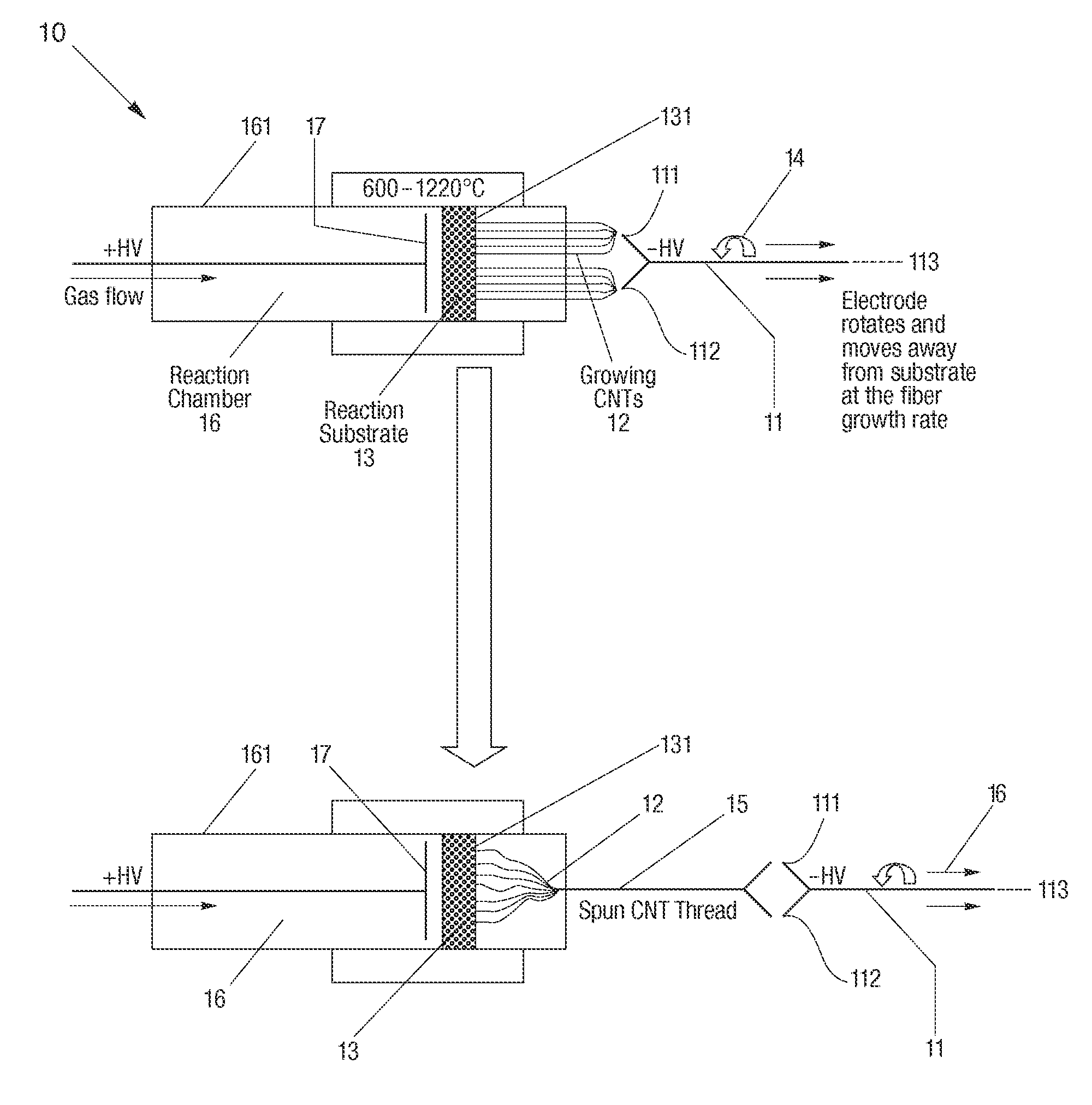
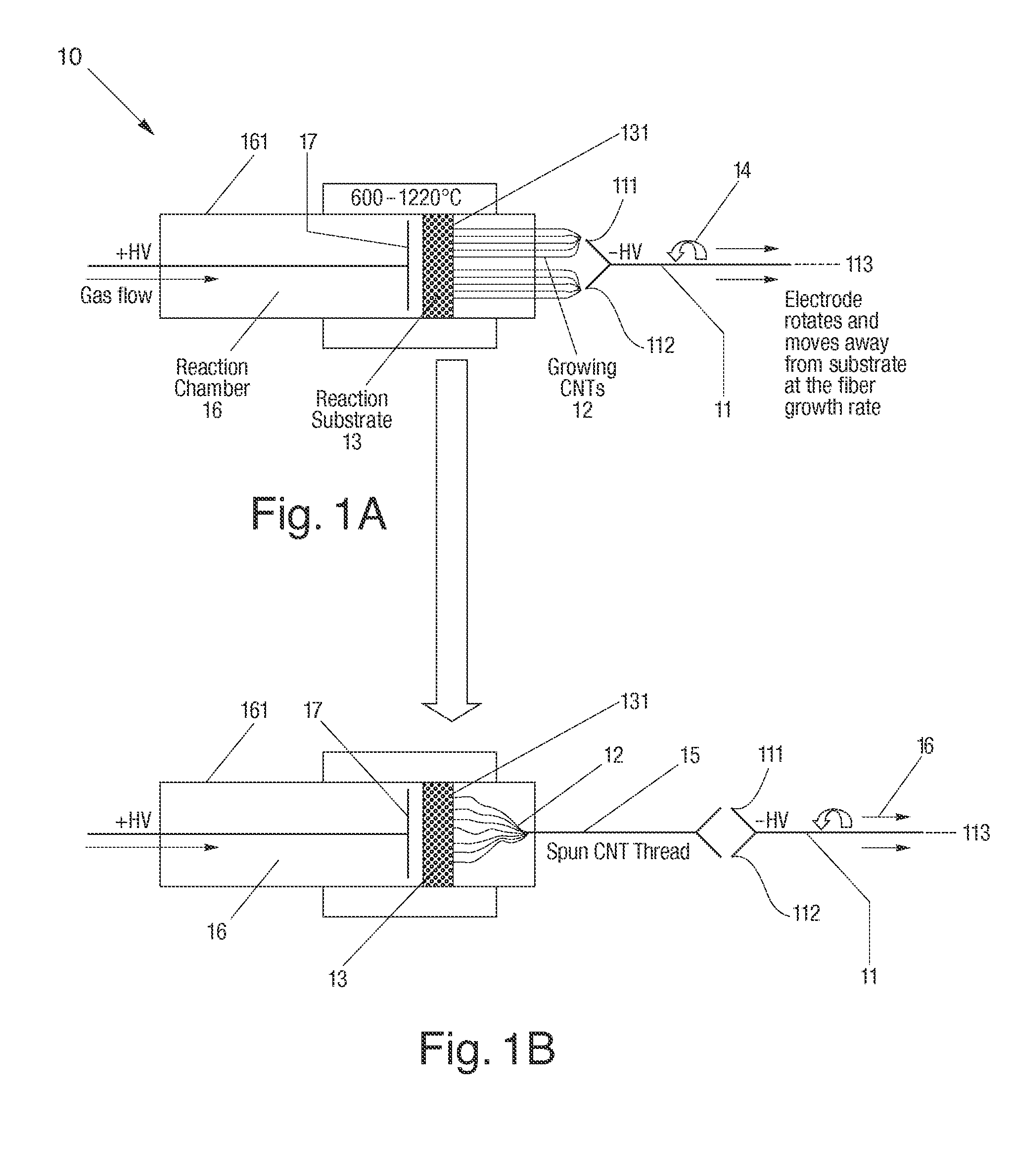
[0013]Carbon nanostructures, such as carbon nanotubes, for use in the manufacturing of an antenna or sensor of the present invention may be fabricated using a variety of approaches. Presently, there exist multiple processes and variations thereof for growing carbon nanotubes. These include: (1) Chemical Vapor Deposition (CVD), a common process that can occur at near ambient or at high pressures, (2) Arc Discharge, a high temperature process that can give rise to tubes having a high degree of perfection, and (3) Laser ablation.

[0014]At present, CVD appears to be one of the more attractive approaches from a commercial standpoint for fabricating carbon nanotubes. However, since growth temperatures for CVD can be comparatively low ranging, for instance, from about 600° C. to about 1300° C., carbon nanotubes, both single wall (SWNT) or multiwall (MWNT), may be grown, in an embodiment, from nanostructural catalyst particles supplied by reagent carbon-containing gases (i.e., gaseous carbon...


PUM

PropertyMeasurementUnit
lengthaaaaaaaaaa
lengthaaaaaaaaaa
frequencyaaaaaaaaaa

Abstract

An antenna for the transmission and reception of electromagnetic radiation is provided. The antenna includes a body portion, which can be flexible to permit incorporation of the antenna into a material. The antenna also includes an aggregate of extended length nanotubes along the body portion, and a plurality of contact points between adjacent nanotubes to permit transmission of electromagnetic radiation, while reducing resistivity along the antenna at a high frequency, for example, above 100 MHz. A method of manufacturing an antenna is also provided.

Description

RELATED U.S. APPLICATION(S)[0001]This application claims priority to U.S. Provisional Patent Application Ser. No. 60 / 733,452, filed Nov. 4, 2005, which application is hereby incorporated herein by reference.TECHNICAL FIELD[0002]The present invention relates to nanostructures, and more particularly, to extended length nanotubes and / or nanotube aggregates for use as an antenna or sensor for the transmission and reception of electromagnetic radiation.BACKGROUND ART[0003]Antennas for transmission and reception need to provide high fidelity information on the nature of the signals received or transmitted. These signals can be distorted in a number of ways, including by the design of the antenna, through its frequency band of operation, and by the manner in which the antenna may be mounted. In addition, signal distortion may be caused by the materials from which the antenna is made. For instance, the materials from which the antenna is made may cause phase distortion. Phase distortion is ...

Claims


Application Information

Patent Timeline
Patent Type & Authority Patents(United States)
IPC IPC(8): H01Q1/36H01Q21/00
CPCB82Y30/00D01F9/127H01Q1/085D01F9/133Y10T29/49016
Inventor LASHMORE, DAVID S.ANTOINETTE, PETER
Owner NANCOMP TECHNOLOGIES INC
Why Eureka
Try Eureka