Dual mode piezoelectric filter, method of manufacturing the same, high frequency circuit component and communication device using the same
a piezoelectric filter and piezoelectric technology, applied in piezoelectric/electrostrictive transducers, generators/motors, devices material selection, etc., can solve the problems of difficult use, low passband, and filter characteristic showing significant insertion loss, etc., to achieve smooth passband and low loss
- Summary
- Abstract
- Description
- Claims
- Application Information
AI Technical Summary
Benefits of technology
Problems solved by technology
Method used
Image
Examples
embodiment 1
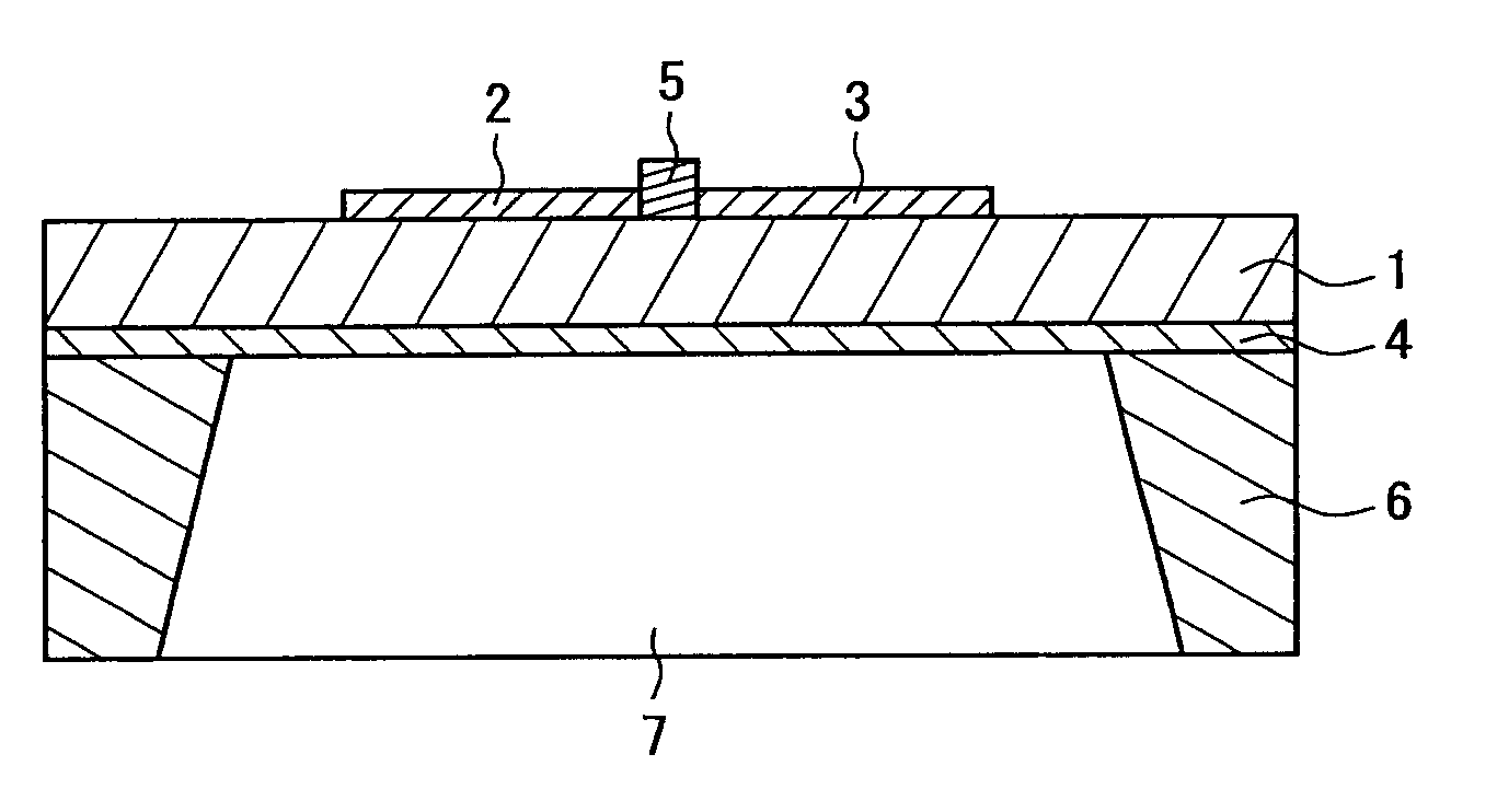
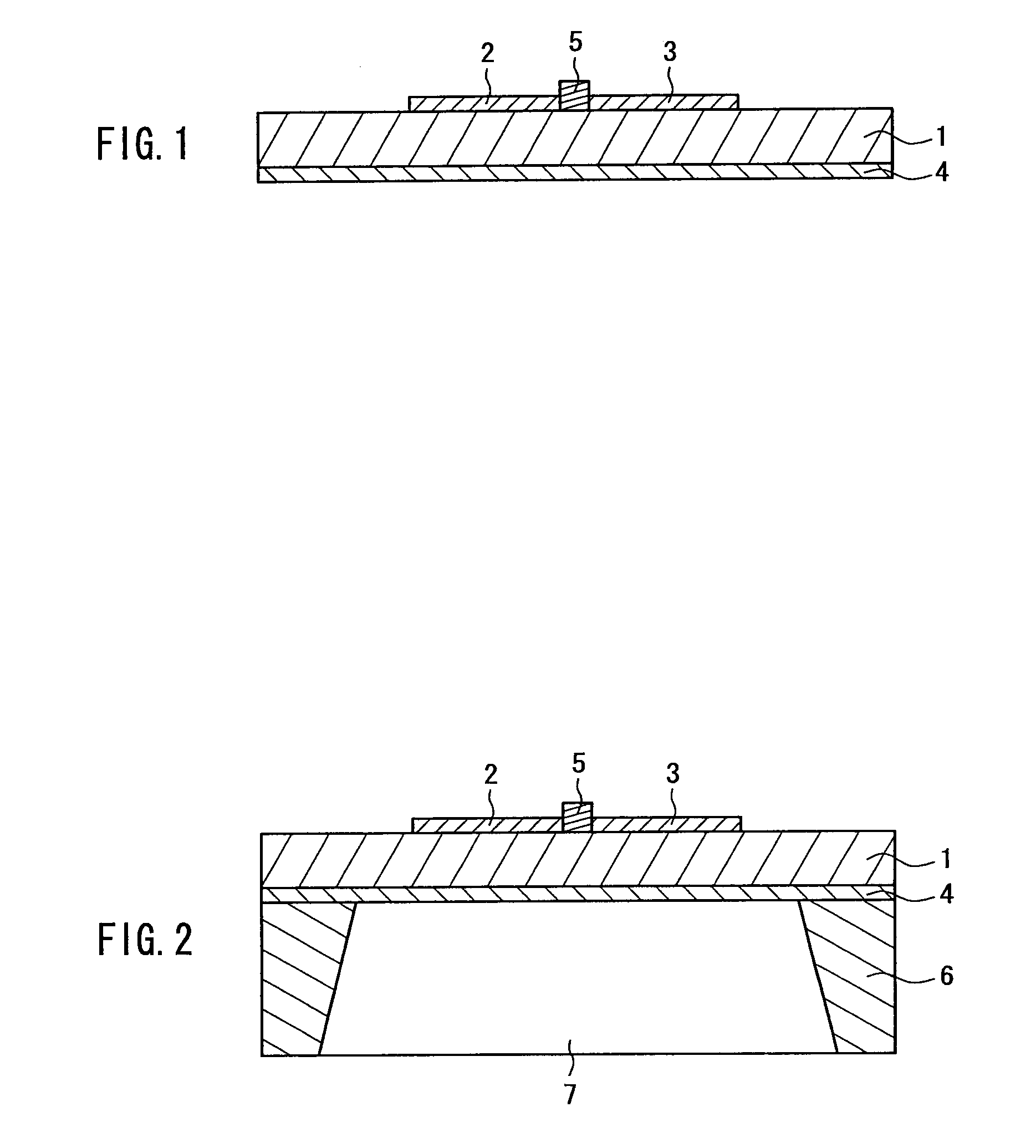
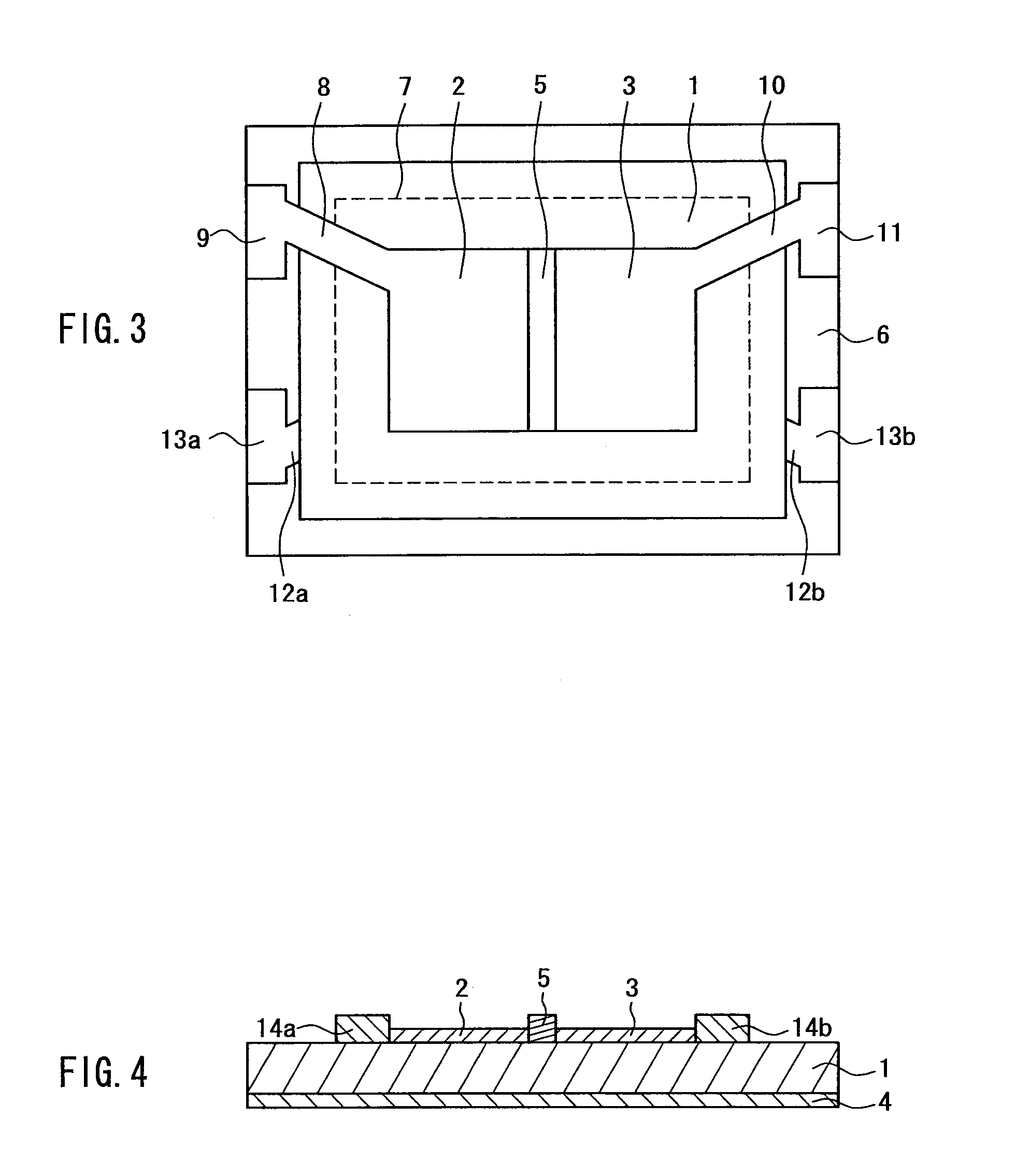
[0076]FIG. 1 is a cross-sectional view illustrating an exemplary construction of a resonant portion of a dual mode piezoelectric filter according to a first embodiment of the present invention. FIG. 2 is a cross-sectional view showing a dual mode piezoelectric filter including a support structure used for the resonant portion illustrated in FIG. 1. FIG. 3 is a top view illustrating an exemplary construction of the dual mode piezoelectric filter illustrated in FIG. 1, including wiring.
[0077]As shown in FIG. 1, in the construction of the resonant portion of the dual mode piezoelectric filter of the present embodiment, a first electrode 2 and a second electrode 3, which serve as input / output electrodes, are formed on a piezoelectric material layer 1 composed of a piezoelectric thin film of the high-cut type, and a first mass load element 5, which constitutes an interelectrode mass load element, is formed in the gap between the first electrode 2 and second electrode 3. Furthermore, a th...
embodiment 2
[0096]FIG. 10 is a cross-sectional view illustrating an exemplary construction of a resonant portion of a dual mode piezoelectric filter according to a second embodiment of the present invention.
[0097]In this resonant portion, a first electrode 2 and a second electrode 3, which serve as input / output electrodes, are formed on top of a high-cut type piezoelectric material layer 1 with a gap provided therebetween, and a third electrode 4, which serves as a grounding electrode, is formed opposite to the first electrode 2, second electrode 3, and the gap between the first electrode 2 and second electrode 3, with the piezoelectric material layer 1 interposed therebetween. Furthermore, a fifth mass load element 20 is formed in a region that faces the gap, so as to be positioned opposite to the gap, with the piezoelectric material layer 1 and third electrode 4 interposed therebetween. Since the first electrode 2 and second electrode 3 are separated spatially in the planar direction, the fir...
embodiment 3
[0108]FIG. 13 is a cross-sectional view illustrating an exemplary construction of a resonant portion of a dual mode piezoelectric filter according to a third embodiment of the present invention.
[0109]In this resonant portion, a first electrode 2 and a second electrode 3 are formed on top of a high-cut type piezoelectric material layer 1, with a first gap provided therebetween, and a fourth electrode 23 and a fifth electrode 24 are formed on the other side of the piezoelectric material layer 1, also with a second gap provided between them. The first electrode 2 and fourth electrode 23, the second electrode 3 and fifth electrode 24, as well as the first gap and second gap, are arranged opposite to one another. Furthermore, an eighth mass load element 25 is formed in the first gap. Since the eighth mass load element 25 is made of an insulating material, the first electrode 2 and second electrode 3 are electrically insulated. Moreover, the fourth electrode 23 and fifth electrode 24 are ...
PUM
| Property | Measurement | Unit |
|---|---|---|
| piezoelectric | aaaaa | aaaaa |
| density | aaaaa | aaaaa |
| thickness | aaaaa | aaaaa |
Abstract
Description
Claims
Application Information
 - R&D
- Intellectual Property
- Life Sciences
- Materials
- Tech Scout
- Unparalleled Data Quality
- Higher Quality Content
- 60% Fewer Hallucinations
Browse by: Latest US Patents, China's latest patents, Technical Efficacy Thesaurus, Application Domain, Technology Topic, Popular Technical Reports.
© 2025 PatSnap. All rights reserved.Legal|Privacy policy|Modern Slavery Act Transparency Statement|Sitemap|About US| Contact US: help@patsnap.com


