
Random number generator and method for generating random numbers

a random number generator and method technology, applied in the direction of form/shuttering/falseworks, shaping building parts, construction, etc., can solve the problems of unfavorable random value distribution, observer or attacker cannot carry out any useful prediction, and the quality of the produced bit stream is not as uniform as desired, so as to improve the quality of the random stream and reduce the power requirement , the effect of low chip area

Active Publication Date: 2010-05-18
INFINEON TECH AG
View PDF9 Cites 3 Cited by
  • Summary
  • Abstract
  • Description
  • Claims
  • Application Information

AI Technical Summary

Benefits of technology

The invention provides a method and apparatus for generating high-quality random numbers with low chip area, low power requirements, and high production yield. The method involves delaying a first signal and sampling and holding it, along with a second signal, to provide random values. The apparatus includes a first signal source, a second signal source, at least one time delay element, and sample and hold elements. The technical effects of the invention include improved random stream quality, reduced chip area and power requirements, and increased production yield and design flexibility.

Problems solved by technology

The most important feature of a high-quality random number generator is the unpredictability of the produced bit stream: an observer or attacker must not be able to carry out any useful prediction about the random number generator's output even if its design is known.
However, only electronic noise sources—such as thermal or shot noise—can be used in an integrated implementation.
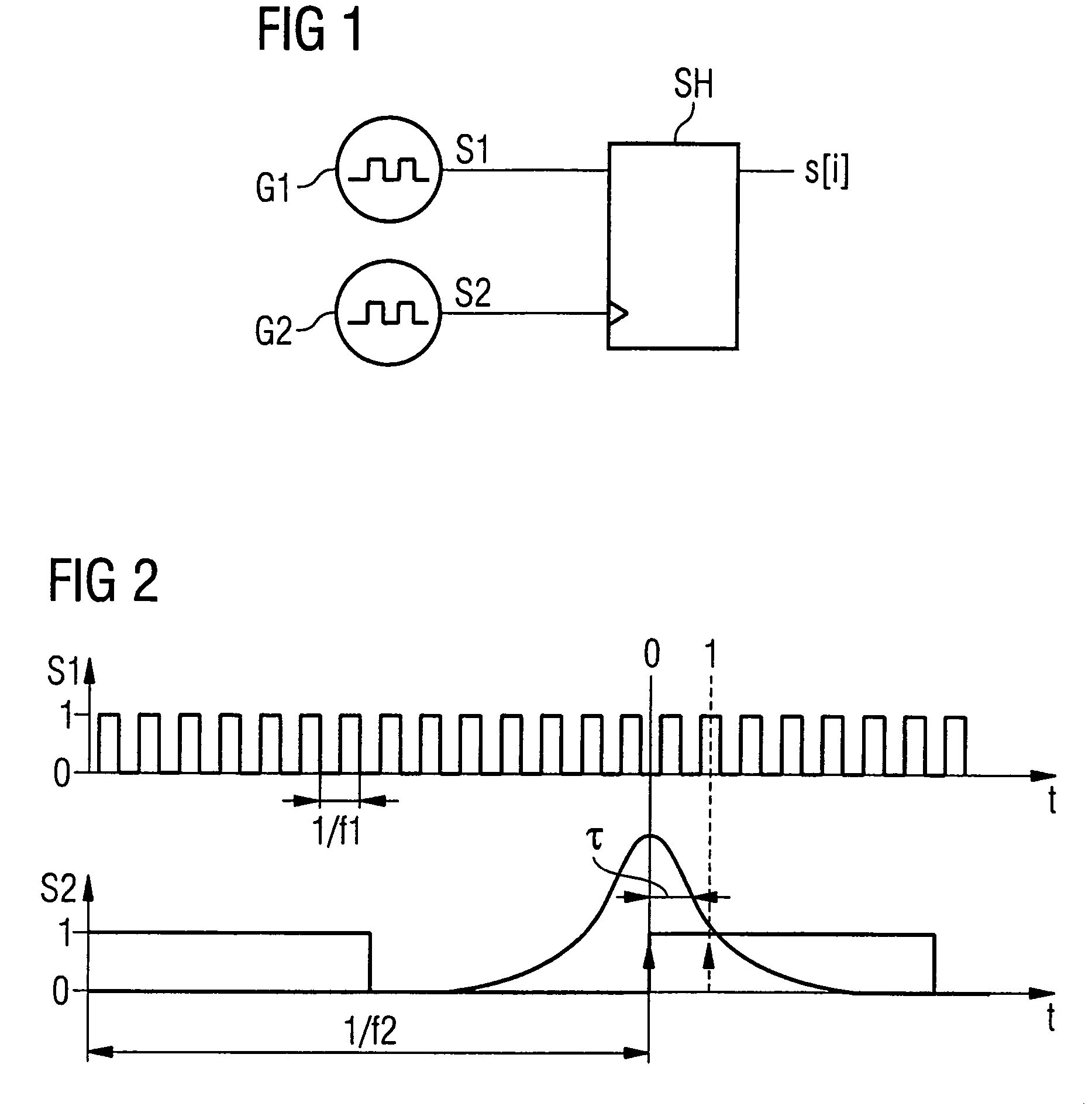
However, the jitter-to-mean-period ratio is usually quite small so that the distribution of the random values is not as uniform as desired.
However, the frequency f1 of the first signal S1 cannot be increased indefinitely because of limits in implementing high-frequency oscillators.
This approach however, results in an increase in chip area and power required for implementation.

Method used


Image

  • Random number generator and method for generating random numbers
  • Random number generator and method for generating random numbers
  • Random number generator and method for generating random numbers

Examples


Embodiment Construction

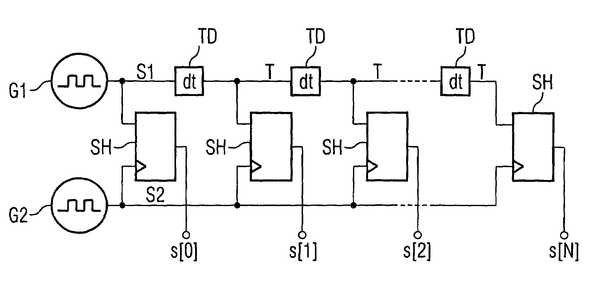
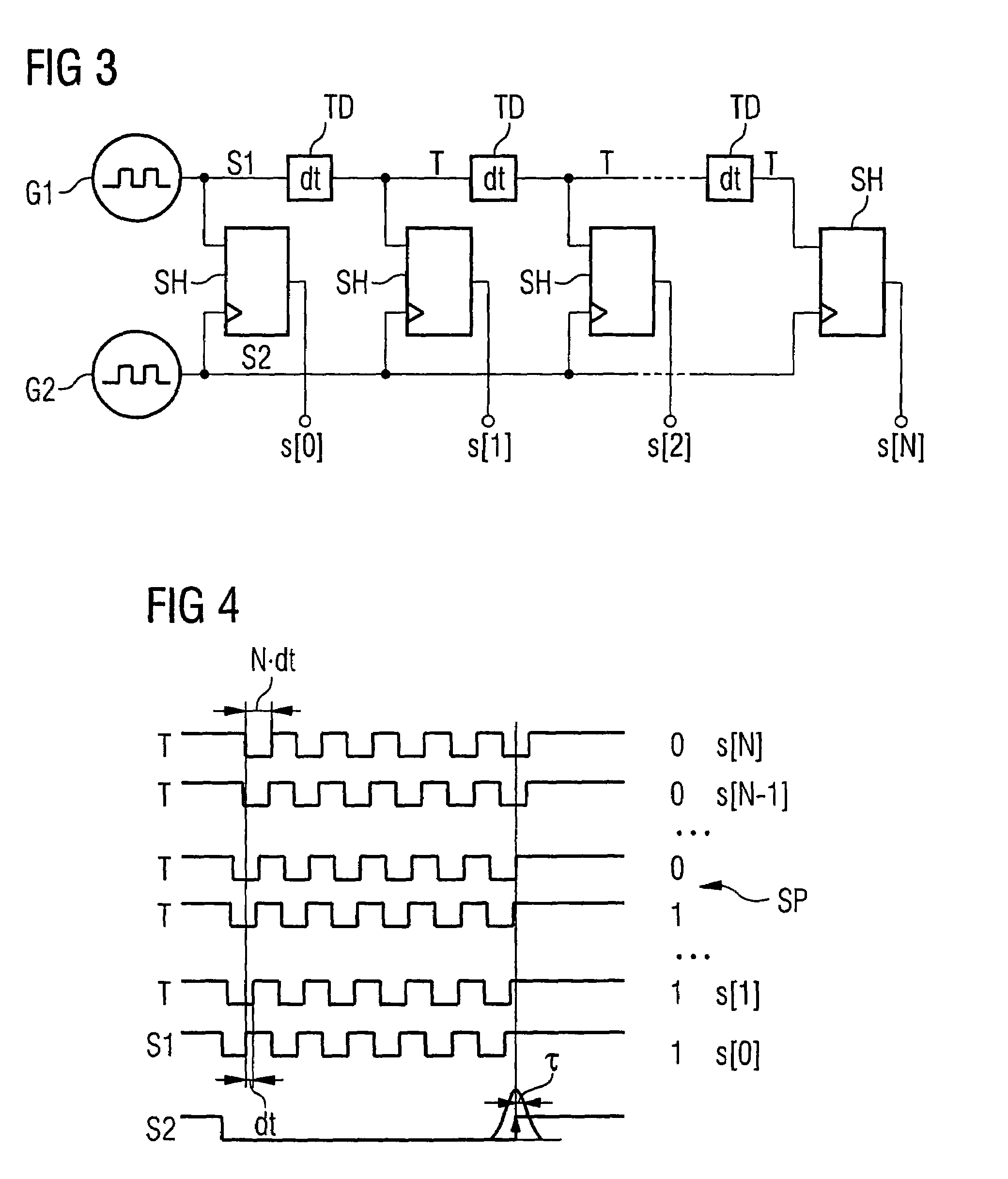
[0023]The invention provides a first method for generating random numbers, comprising the steps of providing a first signal having a first frequency, providing a second signal having a second frequency, the second frequency being lower than the first frequency, delaying the first signal by integer multiples of a time delay to form at least one time-delayed signal, sampling and holding each of the first signal and the at least one time-delayed signal, where the sampling and holding is triggered by the second signal and the sampled and held values are provided as random values.

[0024]By time delaying the first signal N times by a given time delay to give N different time-delayed signals, it is possible to increase the time resolution of the jitter detection, just as if the frequency of the first signal had been increased by a factor of N. Instead of having to increase the jitter of the second signal, the first signal is time-delayed so that at least one of the first signal and the time...


PUM


Abstract

Random number generator including a first signal source outputting a first signal having a first frequency, a second signal source outputting a second signal having a second frequency which is lower than the first frequency, and time delay elements, wherein the output signals are delayed by a time interval with respect to the input signal. The output of one time delay element is connected in series to the input of another time delay element. The input of the first time delay element is connected to the output of the first signal source. The output of the first signal source and the output of each of the time delay elements are connected to the data input of a corresponding sample and hold element. Clock signal inputs of the sample and hold elements are each connected to the output of the second signal source. Outputs of the sample and hold elements provide random values.

Description

CROSS-REFERENCE TO RELATED APPLICATION[0001]This application claims priority to European Patent Application Ser. No. 05001796.1 filed on Jan. 28, 2005.FIELD OF THE INVENTION[0002]The present invention relates to random number generators and to methods for generating random numbers.BACKGROUND OF THE INVENTION[0003]Random numbers are required in many applications. An example is the use of random numbers in cryptographic tokens such as chip-cards. Both the symmetric and asymmetric ciphering algorithms require the availability of a high-quality random number source for key generation. Random numbers are also used for generating challenges in authentification protocols, to create padding bytes and blinding values in random masking.[0004]Pseudo-random number generators based on cryptographic secure deterministic algorithms can be employed for creating random numbers for the above purposes. However, a physical source of true randomness is always needed for algorithm seeding. As a result, a...

Claims


Application Information

Patent Timeline
Patent Type & Authority Patents(United States)
IPC IPC(8): G06F7/58
CPCG06F7/588E04G15/063
Inventor LUZZI, RAIMONDOBUCCI, MARCO
Owner INFINEON TECH AG
Learn More