Catalysts, activating agents, support media, and related methodologies useful for making catalyst systems especially when the catalyst is deposited onto the support media using physical vapor deposition

a technology of catalysts and activating agents, applied in the field of gold-based catalyst systems, can solve the problems of loss of performance and underutilization of nanoporous media, and achieve the effect of dramatically facilitating the use of catalytically active gold and enhancing the performance of catalytic systems

Inactive Publication Date: 2010-06-01
3M INNOVATIVE PROPERTIES CO
View PDF112 Cites 114 Cited by
  • Summary
  • Abstract
  • Description
  • Claims
  • Application Information

AI Technical Summary

Benefits of technology

[0095]Physical vapor deposition typically occurs under temperature and vacuum conditions in which the gold is very mobile. Consequently, the gold is quite mobile and will tend to migrate on the surface of the substrate until immobilized in some fashion, e.g., by adhering to a site on or very near the support surface. It is believed that sites of adhering can include defects such as surface vacancies, structural discontinuities such as steps and dislocations, interfacial boundaries between phases or crystals or other gold species such as small gold clusters. It is a distinct advantage of the invention that the deposited gold is immobilized effectively in a manner in which the gold retains a high level of catalytic activity. This is contrasted to those conventional methodologies in which the gold accumulates into such large bodies that catalytic activity is unduly compromised or even lost.
[0096]There are different approaches for carrying out physical vapor deposition. Representative approaches include sputter deposition, evaporation, and cathodic arc deposition. Any of these or other PVD approaches may be used, although the nature of the PVD technique used can impact catalytic activity. For instance, the energy of the physical vapor deposition technique used can impact the mobility, and hence tendency to accumulate, of the deposited gold. Higher energy tends to correspond to an increased tendency of the gold to accumulate. Increased accumulation, in turn, tends to reduce catalytic activity. Generally, the energy of the depositing species is lowest for evaporation, higher for sputter deposition (which may include some ion content in which a small fraction of the impinging metal species are ionized), and highest for cathodic arc (which may be several tens of percents of ion content). Accordingly, if a particular PVD technique yields deposited gold that is more mobile than might be desired, it may be useful to use a PVD technique of lesser energy instead.
[0097]Physical vapor deposition generally is a line of sight / surface coating technique between the gold source and the support. This means that only the exposed, outer surfaces of the support, but not the inner pores well within the substrate, are directly coated. Inner surfaces not in a direct line of sight with the source will tend not to be directly coated with gold. However, we have found by TEM analysis that after deposition on the surface of a porous substrate, the gold atoms can migrate by diffusion or other mechanism some moderate distance into the catalyst surface to provide nano-particles and gold clusters in the substrate pores in the region immediately adjacent to the surface before being immobilized. The average penetration into the porous substrates can be up to 50 nanometers in depth or sometimes greater, such as up to about 70 to about 90 nm in depth. In general though, the penetration depth is less than 50 nm and can be less than 30 nm. The gold penetration is very shallow compared to the typical support size.
[0098]The total thickness of the gold, or Ct is equal to the gold penetration depth plus the thickness of the gold that is deposited on the surface of the substrate and that has not penetrated by diffusion. This total thickness is in general less than 50 nm and can often be less than 30 nm or even less than 20 nm. On materials having surface pores whose depth is greater than about 10 nm to 20 nm, the total gold thickness can appear to be greater than 50 nm since the gold layer follows the contours of the surface and the actual surface contour is reflected by the pore structure that it possesses. It is most preferred that the active gold species be collected on the outermost portion of the catalyst particle since this is the surface of the catalyst that interacts most readily with gaseous reactants.
[0099]The thickness of the gold shell region relative to the catalyst support particle size is quantified by the formulaPDR=Ct / USTwherein PDR is the penetration depth ratio, UST is the underlying support thickness or particle size and Ct is the total thickness of the gold, as defined above. The underlying support thickness represents the size of the support as measured perpendicular to the catalyst surface and is usually indicative of particle size. The underlying support thickness may be determined by microscopic methods including optical microscopy or scanning electron microscopy. The value for Ct may be determined by transmission electron microscopy in the case of thin films and high resolution scanning electron microscopy in the case of thicker films. The total thickness Ct is very easily discerned from visual inspection of TEM data. Because of the uniformity by which gold is coated, a single representative TEM picture can be effective to characterize the coating. In practice, a sample may be effectively characterized via examination of a number of TEM pictures of catalyst surface cross-sections (vida infra). In preferred embodiments, PDR is in the range of from about 1×10⁻⁹ to 0.1, preferably 1×10⁻⁶ to 1×10⁻⁴, indicating that the gold shell region is very thin indeed relative to total support thickness. As noted above, this generally corresponds to a penetration depth on the order of up to about 50 nm, preferably about 30 nm on preferred supports.
[0100]Characterization of the surface region and the gold bodies is accomplished using transmission electron microscopy as is well-known in the catalyst art. One method suitable for characterizing the catalytic surfaces is as follows: the catalyst particles are embedded in 3M Scotchcast™ Electrical Resin #5 (epoxy; 3M Company, St. Paul, Minn.) in disposable embedding capsules; resin is allowed to cure at room temperature for 24 hours.

Problems solved by technology

However, PVD tends to be a line of sight coating technique, meaning that PVD deposits catalyst mainly at and very near (some minor surface penetration will occur, such as by diffusion) the surface of the nanoporous support media.
From a conventional perspective, the nanoporous media appears to be underutilized, making it appear as if PVD were an inappropriate technique to be used in this context.
In the case of gold, for example, it appears that these nanoscale features help to immobilize the gold, preventing gold accumulation that might otherwise result in a loss of performance.

Method used


Image

  • Catalysts, activating agents, support media, and related methodologies useful for making catalyst systems especially when the catalyst is deposited onto the support media using physical vapor deposition
  • Catalysts, activating agents, support media, and related methodologies useful for making catalyst systems especially when the catalyst is deposited onto the support media using physical vapor deposition
  • Catalysts, activating agents, support media, and related methodologies useful for making catalyst systems especially when the catalyst is deposited onto the support media using physical vapor deposition

Examples


example 1

Type A Gamma Alumina Particles

[0181]Type A gamma alumina particles were treated with gold by plasma-assisted sputtering as previously described using deposition condition 2. The performance of the CO oxidation catalyst of example 1 in oxidizing CO during gas flow through a bed was measured using test method 1. The CO challenge was 3600 ppm CO and the total gas flow rate was 64 liters / min. The gas was at 85% relative humidity. The results are represented in FIG. 6. FIG. 6 and other similar graphs in these examples display measured gas concentrations in ppm versus time of testing after test gas mixture is passed through a 100 ml test bed. The elapsed time is represented in minutes:seconds:tenths of seconds.

example 2

Un-Modified Type B Gamma Alumina Particles

[0182]Type B gamma alumina particles were treated with gold by plasma-assisted sputtering as previously described using deposition condition 2. The performance of the CO oxidation catalyst of example 2 in oxidizing CO during gas flow through a bed was measured using test method 1. The CO challenge was 3600 ppm CO and the total gas flow rate was 64 liters / min. The gas was at 85% relative humidity. The results are represented in FIG. 7.

Impregnation of Gamma Alumina Particles:

[0183]A solution of the impregnation liquid was prepared by mixing sufficient soluble salt of the impregnation metal with deionized water in sufficient quantity to generate a solution having the desired concentration. As an example, to prepare a 0.5 M solution of potassium carbonate (FW=138.21 g / mole), 69.11 g of potassium carbonate was dissolved in sufficient deionized water to yield a final volume of 1 liter.

[0184]The particles were impregnated by incipient wetness. The ...

example 3

Preparation of Potassium Carbonate Impregnated Gamma Alumina Particles—Sample Heated to 130° C.

[0185]710 g of gamma alumina particles A (950 ml volume of gamma alumina particles) was impregnated by the incipient wetness technique using a 0.5 M K2CO3 (Merck KgaA, Darmstadt, Germany) solution. After an addition of 469 ml of the 0.5 M K2CO3 full saturation was achieved. This results in a catalyst support, after drying that is about 2.5% by weight potassium. The particles were dried at 130° C. and a 300 ml portion of this sample was treated with gold (deposition condition 2).

[0186]The weight percent gold on this sample was measured by Inductively Coupled Argon Plasma Spectroscopic Analysis (ICP). The results for replicate samples were 0.0486 wt % gold and 0.0521 wt % gold.

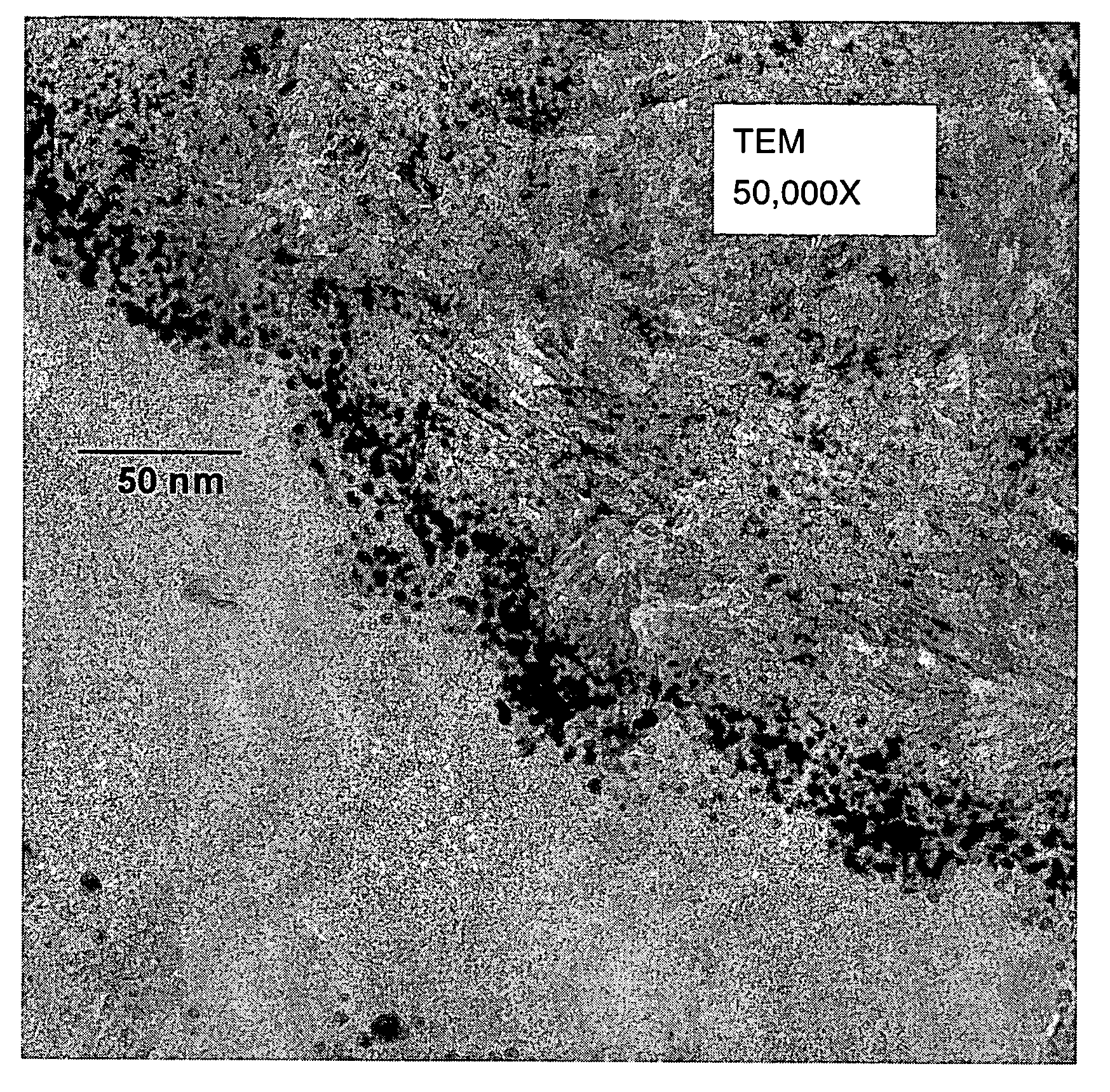
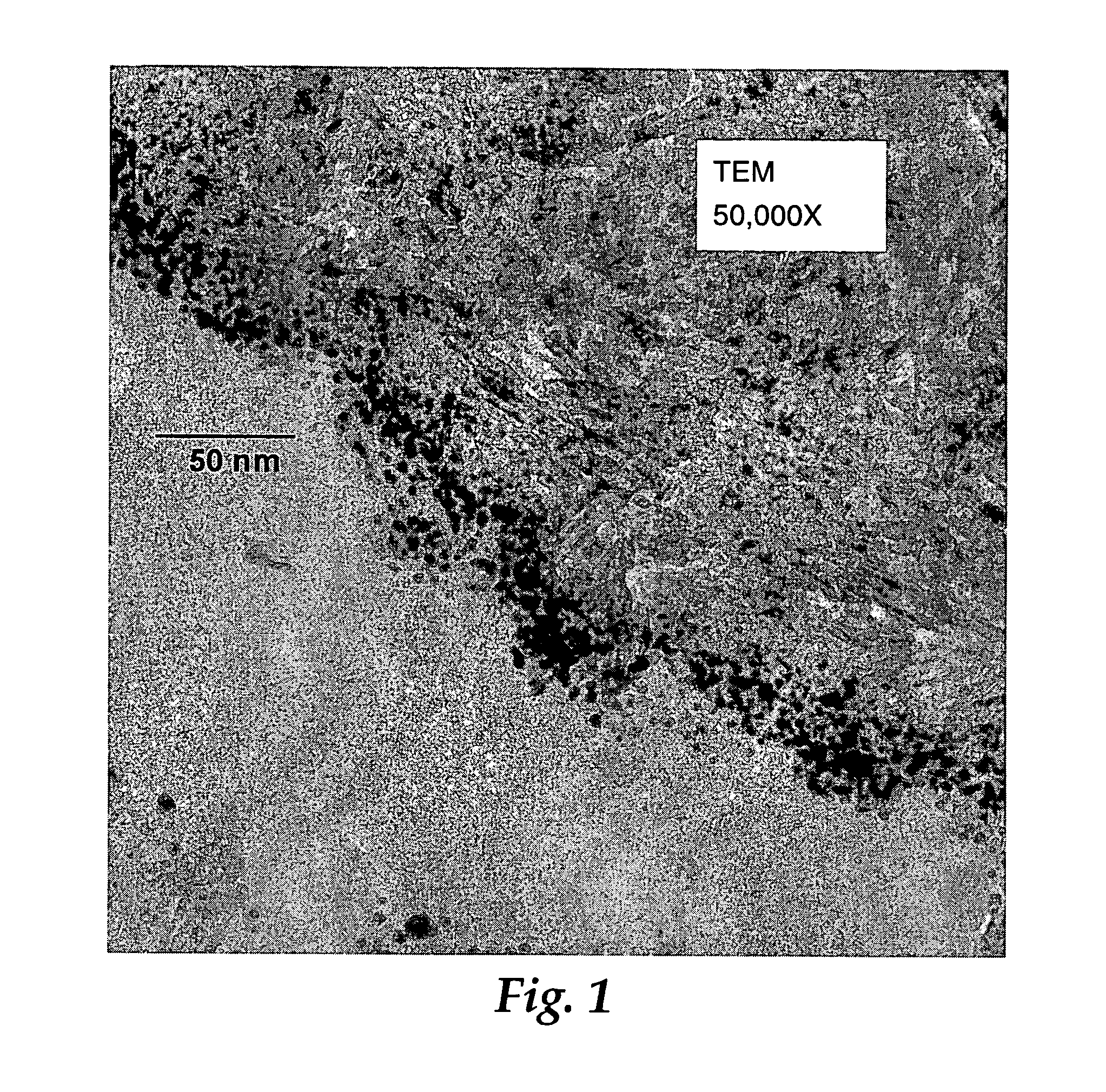
[0187]A sample from Example 3 was examined by TEM as previously described. The approximate size range of Au particles in an undulating region that appeared to be representative of the sample was 2.1 to 6.6 nm. The aver...


PUM


Abstract

Use of physical vapor deposition methodologies to deposit nanoscale gold on activating support media makes the use of catalytically active gold dramatically easier and opens the door to significant improvements associated with developing, making, and using gold-based, catalytic systems. The present invention, therefore, relates to novel features, ingredients, and formulations of gold-based, heterogeneous catalyst systems generally comprising nanoscale gold deposited onto a nanoporous support.

Description

CROSS-REFERENCE TO RELATED APPLICATIONS[0001]The present non-provisional Application claims the benefit of commonly assigned provisional Application having Ser. No. 60 / 506,623, filed on Sep. 26, 2003, and titled CATALYSTS, ACTIVATING AGENTS, SUPPORT MEDIA, AND RELATED METHODOLOGIES USEFUL FOR MAKING CATALYST SYSTEMS ESPECIALLY WHEN THE CATALYST IS DEPOSITED ONTO THE SUPPORT MEDIA USING PHYSICAL VAPOR DEPOSITION, which provisional Application is incorporated herein by reference in its entirety.FIELD OF THE INVENTION[0002]The present invention relates to gold-based catalyst systems, and particularly to gold-based catalyst systems in which nanoscale gold particles are immobilized on nanoporous support media.BACKGROUND OF THE INVENTION[0003]It has been known that ultra-fine, nanoscale gold particles exhibit specific physical and chemical properties different from those of the ordinary coarse gold grains (“Ultra-fine Particles” published by Agne Publishing Center in 1986). In particular,...

Claims


Application Information

Patent Timeline
Patent Type & Authority Patents(United States)
IPC IPC(8): C01G3/00B01D53/14B01D53/56B01D53/94B01J21/00B01J23/00B01J23/02C22B15/00C22B11/00C10K1/00C01G7/00C01G5/00B01J23/04B01J23/06B01J23/58B01J27/055B01J8/00C01B31/18C01B31/20C01B31/24C01D7/37C01B32/50B01D53/86B01J21/04B01J21/06B01J21/18B01J23/52B01J23/66B01J35/00B01J35/02B01J35/10B01J37/02B01J37/34C01B32/40C01B32/60C01B32/942
CPCA62D9/00B01D53/62B01D53/945B01J23/52B01J23/66B01J35/0013B01J35/002B01J35/023B01J37/0238B01J37/347B01J37/349B82Y30/00A62D3/38B01D53/44B01D53/944B01D2255/106B01D2257/502B01J21/04B01J21/18B01J23/02B01J37/0248Y10S977/903Y10S977/90Y10S977/904Y10S977/963Y02T10/22B01J35/006Y02A50/20Y02T10/12B01J21/02
Inventor BREY, LARRY A.WOOD, THOMAS E.BUCCELLATO, GINA M.JONES, MARVIN E.CHAMBERLAIN, CRAIG S.SIEDLE, ALLEN R.
Owner 3M INNOVATIVE PROPERTIES CO
Why Eureka
Try Eureka