Apparatus on a spinning preparation machine for ascertaining the mass and/or fluctuations in the mass of a fibre material

a preparation machine and apparatus technology, applied in the direction of fibre treatment, safety devices for fibre treatment, textiles and paper, etc., can solve the problems of insufficient space, inability to measure the mass of a given material, etc., to achieve improved and accurate measurement, small dimensions, and high frequency/cv values

Inactive Publication Date: 2010-06-15
TRUETZSCHLER GMBH & CO KG
View PDF46 Cites 2 Cited by
  • Summary
  • Abstract
  • Description
  • Claims
  • Application Information

AI Technical Summary

Benefits of technology

[0010]The contactless distance sensor according to the invention allows improved and accurate measurement in a structurally simple way. Instead of an inductive field there are used electromagnetic waves, especially light waves, for example lasers, or acoustic waves, for example ultrasound. The use of light, especially laser light, allows focussed scanning of the measuring tongue or of a counter-element associated with the measuring tongue, so that the measuring tongue can have small dimensions and allows high frequencies / CV values to be detected. That advantage is also obtained when lightweight non-metallic materials are used for the feeler element, for example ceramics, fibre-reinforced materials or the like. The evaluation can take place either in the vicinity of the measuring point or in a control box if the optical signals are conducted from the measuring point to the evaluating unit by means of optical waveguides. Further advantages are obtained as a result. Because the optical waveguide is not subject to any inductive interference effects, a connection in accordance with EMC guidelines becomes unnecessary. Such contactless distance measurement also ensures that measurement can be absolutely precise. The measurement is wear-free, temperature-independent, free of electrical interference effects (measurement data are transported by light guides) and contaminants are avoided by virtue of the continuous cleaning of the measuring funnel. In addition to the advantage of the very simple installation of the optical distance sensor and / or the optical waveguides, it is additionally possible, depending upon the measuring process, to carry out fresh calibration of the measuring funnel at any time using an existing control means that evaluates the measurement signal. The calibration of the measuring funnel is effected on initial start-up. A further advantage is that the measurement path of the feeler tongue excursion is programmable to be fixed or variable. A further advantage is the considerable reduction in the weight of the feeler tongue. Because it is possible to use an optical distance sensor / optical waveguide to view any point of the feeler tongue inside the measuring funnel, the weight of the feeler tongue can be reduced to an absolute minimum (allowing for a new measuring method for high frequencies). The resulting reduction in weight allows a substantially higher sensing frequency of the feeler tongue, because its natural resonance is shifted towards a higher frequency. Accordingly, the control means is also able to ascertain and display very high realistic CV values.
[0011]On the basis of such a contactless measuring process it is also possible to implement the measurement of the fibre material using a driven tongue-and-groove roller. In addition to improved sliver quality resulting from the transport of the fibres, a further advantage is that the driven tongue-and-groove roller can replace a separate delivery roller and can therefore fulfil two functions at the same time (measurement of the fibre density and transport of the fibre material). By virtue of this measure, an output measuring funnel and condenser become entirely unnecessary. As a result of the contactless distance measurement, the measurement point for ascertaining the fibre density at the delivery rollers (tongue / groove) can be directly at the rollers or alternatively on the roller journals.

Problems solved by technology

A disadvantage is that such displacement sensors are electrically connected to a shielded control line by way of a special inbuilt connector.
A further problem is that the sensor is temperature-dependent.
In addition, the amount of space required for certain applications, in which small dimensions are a factor, is too large.

Method used


Image

  • Apparatus on a spinning preparation machine for ascertaining the mass and/or fluctuations in the mass of a fibre material
  • Apparatus on a spinning preparation machine for ascertaining the mass and/or fluctuations in the mass of a fibre material
  • Apparatus on a spinning preparation machine for ascertaining the mass and/or fluctuations in the mass of a fibre material

Examples


Embodiment Construction

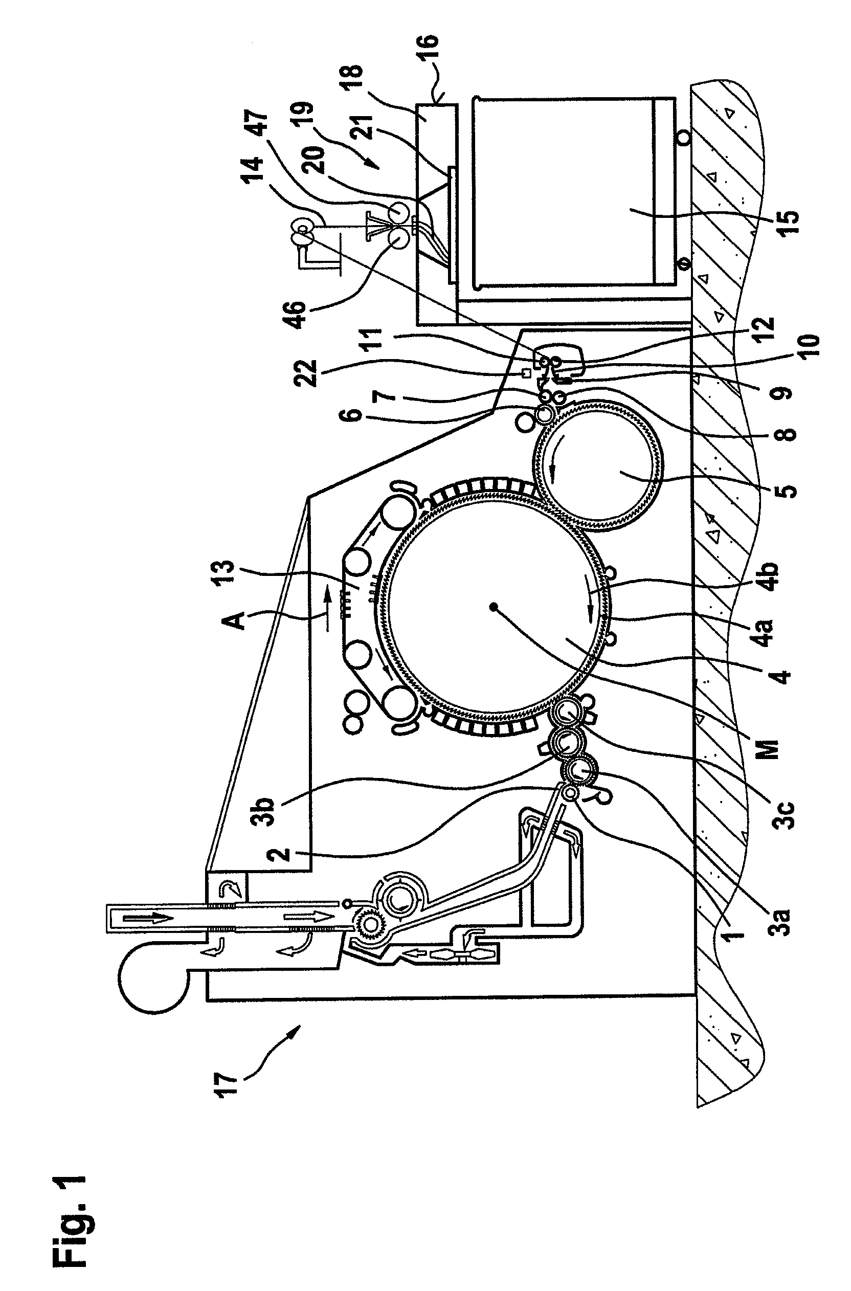
[0035]FIG. 1 shows a flat card, e.g. a flat card known as TC03™ made by Trützschler GmbH & Co. KG of Mönchengladbach, Germany, having a feed roller 1, feed table 2, lickers-in 3a, 3b, 3c, cylinder 4, doffer 5, stripper roller 6, nip rollers 7, 8, web guide element 9, web funnel 10, delivery rollers 11, 12, revolving card top 13 with card top guide rollers and card flat bars, can 15 and can coiler 16. A fibre bundle passes through the web funnel 10, the fibre bundle entering in the form of a fibre web (not shown) and being discharged in the form of a card sliver 14. The directions of rotation of the rollers are indicated by curved arrows. Reference letter M denotes the centre point (axis) of the cylinder 4. Reference numeral 4a indicates the clothing and reference numeral 4b indicates the direction of rotation of the cylinder 4. Arrow A indicates the working direction. A tuft feed device 17 is arranged upstream of the flat card. The coiling plate 19 is rotatably mounted in the coilin...


PUM

PropertyMeasurementUnit
angleaaaaaaaaaa
massaaaaaaaaaa
distancesaaaaaaaaaa

Abstract

In an apparatus on a spinning preparation machine, for example a flat card, roller card, draw frame, combing machine or the like, for ascertaining the mass and / or fluctuations in the mass of a fiber material, for example at least one fiber sliver, fiber web or the like, of cotton, synthetic fibers or the like, the fiber material is scanned mechanically by a feeler element the excursions of which are converted into electrical signals. In order to facilitate improved and more accurate measurement of the fiber in a way that is simple in terms of structure and installation, a contactless distance sensor is provided for detecting the position of the feeler element, the sensor being a sensor that measures distance using transmitted waves, and is connected to an electronic evaluating device.

Description

CROSS REFERENCE TO RELATED APPLICATION[0001]This application claims priority from German Patent Application No. 10 2005 023 992.7, dated May 20, 2005, the entire disclosure of which is included herein by reference.BACKGROUND OF THE INVENTION[0002]The invention relates to an apparatus on a spinning preparation machine, for example a flat card, roller card, draw frame, combing machine or the like, for ascertaining the mass and / or fluctuations in the mass of fibre material, for example at least one fibre sliver, fibre web or the like, of cotton, synthetic fibres or the like.[0003]The invention relates to the contact pressure of a feeler device on a fibre bundle in a sliver guide means, such as is used for measuring the thickness of fibre bundles on a textile machine. Such a textile machine can be a flat card, a draw frame, a flyer or a combing machine. The contact pressure of the feeler device is important for the formation of a correct measurement signal relating to the thickness of t...

Claims


Application Information

Patent Timeline
Patent Type & Authority Patents(United States)
IPC IPC(8): D01H5/32
CPCD01G23/06D01H5/38D01G31/006D01H13/32G01B21/12
Inventor DUDA, GUNTERMINTER, FRANZ-JOSEF
Owner TRUETZSCHLER GMBH & CO KG
Why Eureka
Try Eureka