Reflective semiconductor optical amplifier (RSOA), RSOA module having the same, and passive optical network using the same

a technology of semiconductor optical amplifier and reflector, which is applied in the field of passive optical network, can solve the problems of increasing the cost of wdm-pon, limiting the number of subscribers, and unable to transmit content, so as to improve the economic efficiency and practical use of bandwidth, reduce light loss, and improve polarization dependency

Inactive Publication Date: 2010-06-15
ELECTRONICS & TELECOMM RES INST
View PDF9 Cites 14 Cited by
  • Summary
  • Abstract
  • Description
  • Claims
  • Application Information

AI Technical Summary

Benefits of technology

[0025]The present invention also provides an RSOA module using the RSOA, for improving polarization dependency.
[0026]The present invention also provides a Passive Optical Network (PON) using the RSOA, for increasing economical efficiency and practical use of a bandwidth.
[0046]The RSOA includes the p-type electrode which is divided into the two portions, thereby reducing light loss due to an optical link. The RSOA module using the RSOA includes the waveplate inserted into the PLC platform, thereby improving polarization dependency. The PON uses a common optical fiber for the transmission of the upstream signal and the downstream signal between the remote node and the ONT and between the central office and the remote node and includes a TDM splitter in the remote node, thereby increasing the economical efficiency and practical use of a bandwidth.

Problems solved by technology

However, since intrinsic wavelengths are respectively assigned to subscribers for communication with the CO, the WDM-PON has a limited wavelength band and interval, and thus, the number of subscribers is also limited.
Moreover, although a transmission speed per wavelength is at least 1 Gbps, there is no content to be transmitted for which this high speed is appropriate.
From an economical point of view, the WDM-PON is more expensive since it requires a pair of optical transceiver modules for each subscriber, which are respectively installed in a subscriber's area and the CO.
In addition, the WDM-PON requires optic sources having intrinsic wavelengths, the number of which is identical to the number of subscribers, so that an economical burden is imposed on subscribers and, therefore, implementation of the WDM-PON is difficult.
From a maintenance point of view, the service provider is disadvantaged in that it must prepare different optic sources having different wavelengths for individual subscribers for installation and breakdowns.
Usually, an active region in an RSOA has an indium gallium arsenide phosphide (InGaAsP) bulk structure because it is not easy to reduce polarization-dependent gain (PDG) by controlling stress at a quantum well region in the multiple quantum well structure.
For this reason, the price of RSOA modules increases and the reliability thereof decreases.
However, as described above, when the multiple quantum well structure is used, it is necessary to precisely control polarization of light input to an RSOA by an optical link or to use unpolarized light due to a PDG problem.
Briefly, the multiple quantum well structure has excellent gain, saturation and temperature characteristics but has a PDG problem, while the bulk structure can reduce PDG when a tensile stress is appropriately applied during the growth of an active region but has poor gain, saturation and temperature characteristics.
The passive alignment method enables easier alignment than the active alignment method, thereby being suitable for mass production, but is disadvantageous in that it needs expensive flip-chip bonding equipment and precise fabrication of a V-groove.

Method used


Image

  • Reflective semiconductor optical amplifier (RSOA), RSOA module having the same, and passive optical network using the same
  • Reflective semiconductor optical amplifier (RSOA), RSOA module having the same, and passive optical network using the same
  • Reflective semiconductor optical amplifier (RSOA), RSOA module having the same, and passive optical network using the same

Examples


Embodiment Construction

[0066]The present invention will now be described more fully with reference to the accompanying drawings, in which exemplary embodiments of the invention are shown. It will be understood that when a layer is referred to as being “on” another layer or substrate, it can be directly on the other layer or substrate, or intervening layers may also be present. In the drawings, the thicknesses and sizes of layers are exaggerated for clarity and irrelevant parts are omitted. The invention may, however, be embodied in many different forms and should not be construed as being limited to the embodiments set forth herein; rather, these embodiments are provided so that this disclosure will be thorough and complete, and will fully convey the concept of the invention to those skilled in the art. Like reference numerals in the drawings denote like elements.

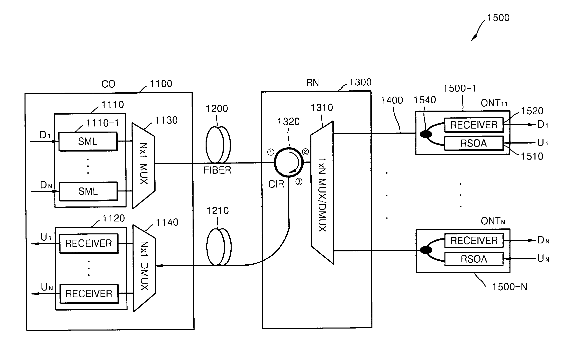
[0067]Conventional Wavelength Division Multiplexing Passive Optical Network (WDM-PON) systems have disadvantages such as restriction of waveleng...


PUM


Abstract

A Reflective Semiconductor Optical Amplifier (RSOA) for compensating for light loss in an optical link, an RSOA module for improving polarization dependency using the RSOA, and a Passive Optical Network (PON) for increasing economical efficiency and practical use of a bandwidth using the RSOA are provided. The PON includes a central office comprising a plurality of optic sources transmitting a downstream signal and a plurality of first receivers receiving an upstream signal; at least one optical network terminal (ONT) including a second receiver receiving the downstream signal and an RSOA which receives the downstream signal, remodulates the downstream signal into the upstream signal, and transmits the upstream signal in loopback mode; and a remote node interfacing the central office with the ONT. The upstream signal and the downstream signal are transmitted between the remote node and the ONT via a single optical fiber. The remote node includes an optical power splitter at its port connected to the ONT.

Description

CROSS-REFERENCE TO RELATED PATENT APPLICATIONS[0001]This application claims the benefit of Korean Patent Application Nos. 10-2005-0121025, filed on Dec. 9, 2005 and 10-2006-49022, filed on May 30, 2006, in the Korean Intellectual Property Office, the disclosures of which are incorporated herein in their entirety by reference.BACKGROUND OF THE INVENTION[0002]1. Field of the Invention[0003]The present invention relates to a Passive Optical Network (PON), and more particularly, to a Reflective Semiconductor Optical Amplifier (RSOA), an RSOA module having the RSOA, and a PON using the RSOA.[0004]2. Description of the Related Art[0005]Fiber To The Home (FTTH) technology for directly connecting a telephone switch to a home through optical fiber has been actively researched and developed worldwide in order to provide voice, data, and broadcast convergence services to subscribers and is expected to become popular within a few years. From the point of view of the characteristics of an optica...

Claims


Application Information

Patent Timeline
Patent Type & Authority Patents(United States)
IPC IPC(8): H01S3/00
CPCB82Y20/00G02B6/4202G02B6/4204H01S5/0425H01S5/5018H04J14/0226H04J14/0282H04J14/0246H04J14/0247H04J14/025H04J14/0252G02B6/12004H04J2014/0253H01S5/101H01S5/1014H01S5/34
Inventor KIM, BYOUNG WHIPARK, MAHN YONGLEE, WOO-RAMKIM, TAE YEON
Owner ELECTRONICS & TELECOMM RES INST
Why Eureka
Try Eureka