Ionization vacuum gauge

a vacuum gauge and ionization technology, applied in vacuum gauges, fluid pressure measurement, instruments, etc., can solve the problems of inaccurate pressure measurement, non-uniformity of vacuum products, defective products, etc., and achieve the effect of improving pressure measurement accuracy and controlling accurately

Inactive Publication Date: 2010-06-22
MIRAPRO
View PDF8 Cites 12 Cited by
  • Summary
  • Abstract
  • Description
  • Claims
  • Application Information

AI Technical Summary

Benefits of technology

[0028]Thus, the problem can be solved by creating conditions in that adsorption of pollutant molecules and decomposed material molecules is not caused by using the heating means which can independently raise the temperature of the ion collector by, for example, electric current heating.
[0038]And, since it is possible to divert the ion collector electrode as the pressure measurement element of the Pirani gauge, there is also an effect that the pressure of a wide range of from the atmospheric pressure to 10−9 Pa can be measured by a single probe.

Problems solved by technology

But, when the ionization vacuum gauge repeats the opening to the atmosphere or is used in a gas composition environment containing pollutant molecules (often organic matter), sensitivity S of the ionization vacuum gauge lowers, causing a problem that the pressure cannot be measured accurately.
Therefore, products produced in vacuum are in non-uniformity or include defective ones, and the inaccuracy of the pressure measurement by the ionization vacuum gauge is now a serious problem in the industry.
Therefore, there is used an uneconomical technology that the probe of the ionization vacuum gauge is exchanged periodically.
But, the use of such a method involves lowering of the sensitivity until the probe is exchanged, and the accurate pressure measurement is not performed.
And, the electrons become hard to flow into the grid, the electron current Ie of the formula (1) is disturbed, and the sensitivity is deteriorated.
Otherwise, there is a possibility that a large amount of gas is discharged just when the electron bombardment heating is started, an electric discharge phenomenon occurs to destroy the electron source, and the power supply connected to them is damaged.
Therefore, when the ionization vacuum gauge is used in a vacuum environment where pollutant molecules are generated, pollutant molecule ions in large quantity are generated by cleaning with the electron bombardment heating, resulting in a possibility of conversely increasing the pollution.
But, they are not the methods to keep heating at all times and cannot freely change the temperature of the grid 2, so that if lowering of the sensitivity occurs when measuring, it is apparent that the pressure is low correspondingly and an incorrect pressure is measured.
But, in the case of pollutant ions, they have a large molecular weight and often remain on the ion collector.
Since they are active and have a tendency to cause a polymerization reaction on the ion collector, they change to a substance having a larger molecular weight and become an insulator which hardly allows the flow of electricity when the reaction occurs.
This is the cause, of lowering the sensitivity.
But, the triode type ionization vacuum gauge is hardly used today because a pressure measurement limit inherent to an ionization vacuum gauge and called as X-ray limit is high to about 10−6 P, and the pressure of the ultrahigh vacuum region cannot be measured.
If the pressure is higher than the above, the function as the ionization vacuum gauge is lost, and a damage due to oxidation of the hot-cathode filament is easily caused.
Therefore, when this oxide-coated filament is used as a resistor of the Pirani gauge, the surface is porous and heat conduction is also poor, so that the heat exchange with gas molecules is deteriorated, resulting in a problem of poor stability.
Since the line diameter is too thick as the resistor of the Pirani gauge, a pressure range usable for measuring becomes very small.
Therefore, it cannot be said that the above two disclosed known technologies are practical.

Method used


Image

  • Ionization vacuum gauge
  • Ionization vacuum gauge
  • Ionization vacuum gauge

Examples


Embodiment Construction

[0049]Embodiments of the invention will be described in detail below with reference to the drawings.

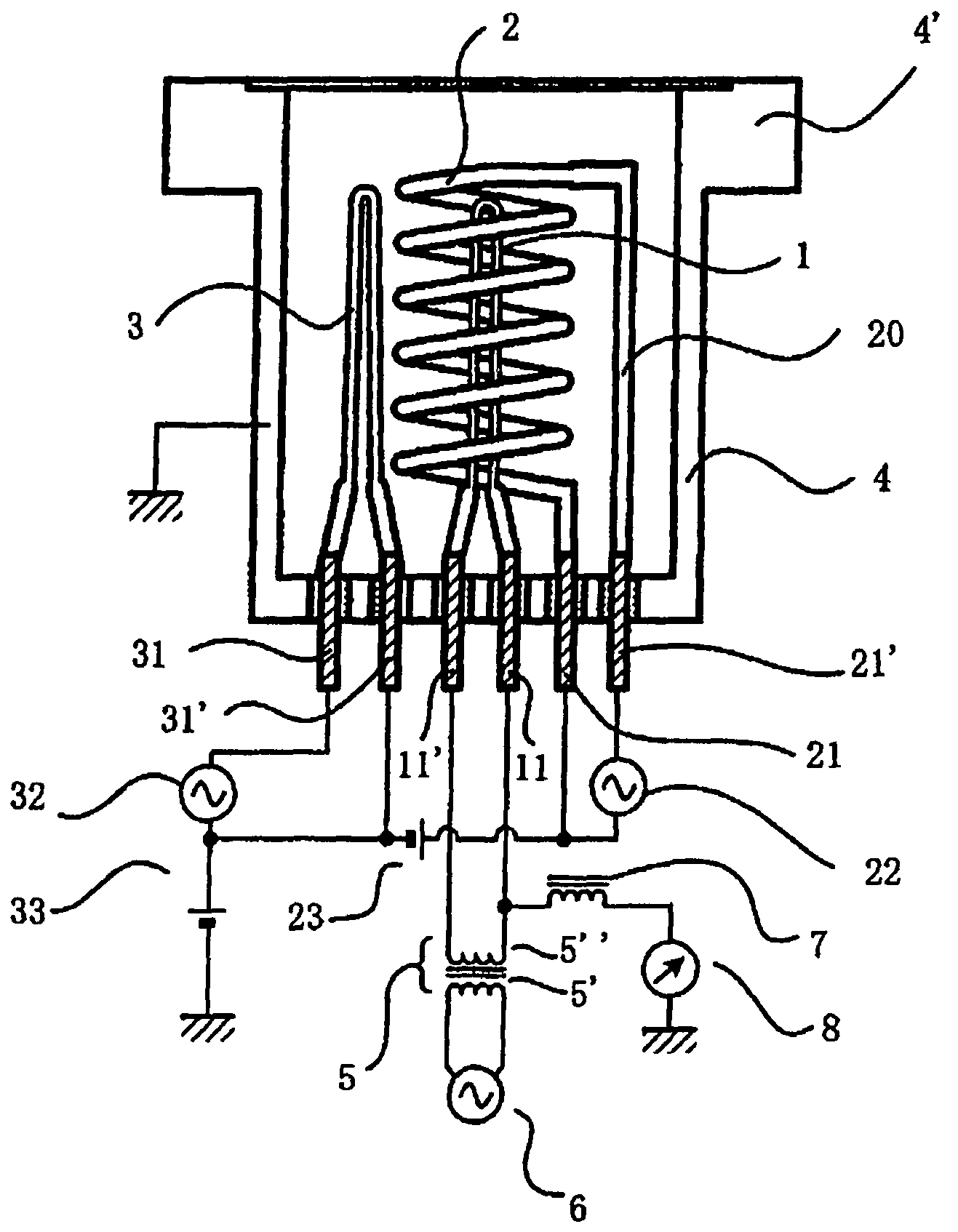
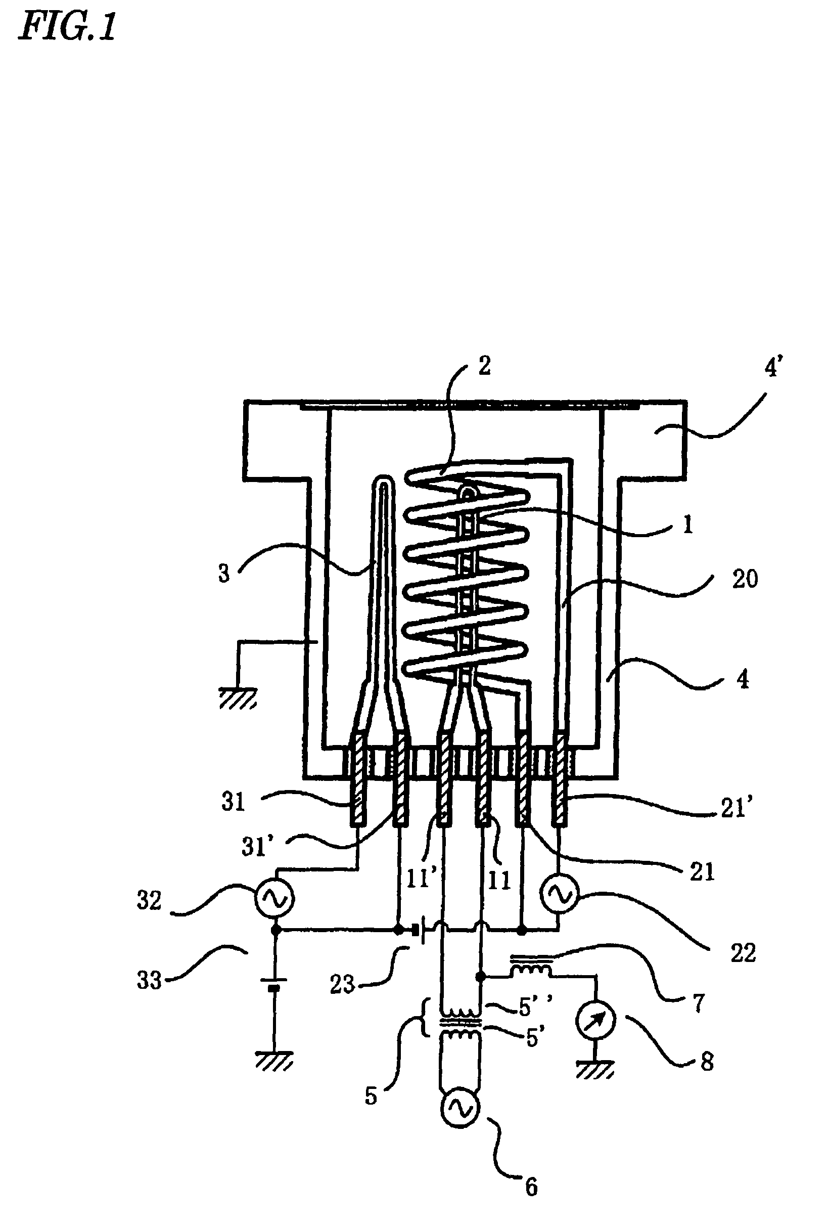
[0050]FIG. 1 shows an example that the BA type ionization vacuum gauge according to the invention is fitted to a vacuum apparatus (not shown). Like constituting elements as those shown in FIG. 10 are denoted by same reference numerals.

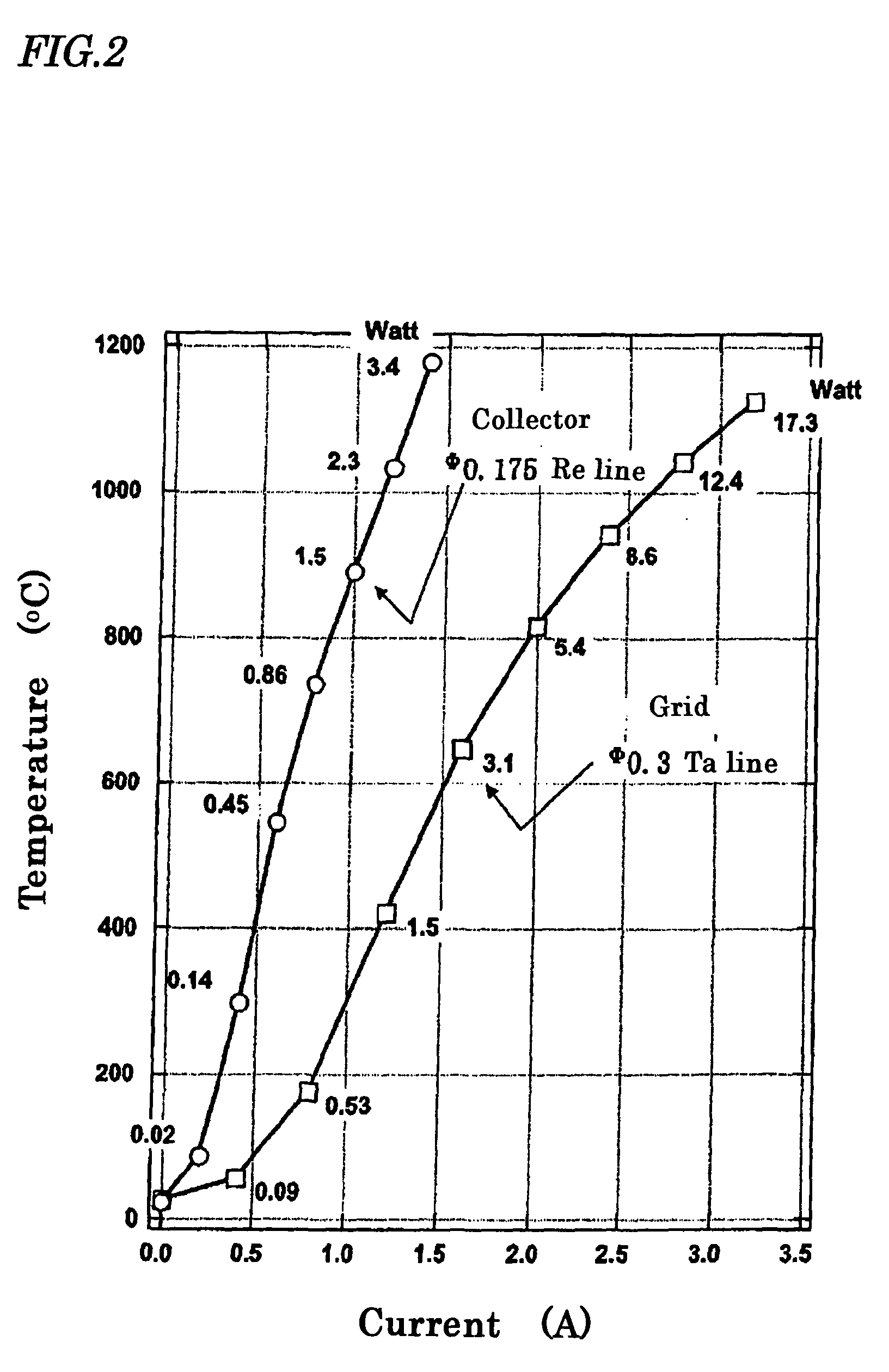
[0051]A grid 2 has a shape that a tantalum wire having a line diameter of Φ0.3 mm is wound nine turns into a spiral shape having an inner diameter of 6 mm. One end of the spiral line is connected to a feedthrough terminal 21, and the other end is connected to another feedthrough terminal 21′ through a support electric wire 20. The two terminals are connected to a voltage-variable AC power supply 22 for heating the grid.

[0052]As shown in FIG. 2, the grid 2 of the above-described size can independently raise a temperature up to about 500° C. when a current of 1.4 A (2.3 W) is flowed to the grid 2, and up to 1000° C. when a current of 2.6 A (10.5 W) is flow...


PUM

PropertyMeasurementUnit
surface temperatureaaaaaaaaaa
pressureaaaaaaaaaa
temperatureaaaaaaaaaa

Abstract

An ionization vacuum gauge which has at least three electrodes of a grid (2), an electron source (3) and an ion collector (1) in a vacuum vessel (4) connected in communication with a vacuum apparatus, oscillates electrons emitted front the electron source (3) within and outside of the grid (2), ionizes gas molecules flying into the grid (2) by the oscillated electrons, supplements the ionized ions by the ion collector (1) to convert into a current signal, and measures a gas molecular density (pressure) in the vacuum apparatus according to the obtained current intensity, wherein the ion collector (1) is provided with a heating device for heating the ion collector.

Description

TECHNICAL FIELD[0001]The present invention relates to an ionization vacuum gauge for measuring a gas molecular density, namely a pressure, of gas molecules within a vacuum apparatus.PRIOR ART[0002]As a typical example of measuring a gas density (pressure) remaining in the vacuum apparatus, a related art will be described with reference to an ionization vacuum gauge shown in FIG. 10.[0003]This ionization vacuum gauge is called a Bayard-Alpert type ionization vacuum gauge (hereinafter referred to as the BA type), which is generally capable of measuring a very wide pressure range of 0.1 Pa to 10−9 Pa and now most popular.[0004]This ionization vacuum gauge has three electrodes of a grid 2, an electron source 3 and an ion collector 1′ within a vacuum vessel 4 connected in communication with a vacuum apparatus, oscillates the electrons emitted from the electron source 3 within and outside of the grid 2, ionizes the gas molecules which fly into the grid 2 by the oscillated electrons, suppl...

Claims


Application Information

Patent Timeline
Patent Type & Authority Patents(United States)
IPC IPC(8): G01L21/32
CPCH01J41/04G01L21/32
Inventor WATANABE, FUMIOWATANABE, REIKI
Owner MIRAPRO
Why Eureka
Try Eureka