Self-protected, intelligent, power control module

a power control module and self-protection technology, applied in the field of electric power control, can solve the problems of destructive voltage spikes, high cost of mechanical relays, arching and sparking of mechanical relays, etc., and achieves low output terminal resistance, corrosion resistance and compactness.

Inactive Publication Date: 2010-06-22
SHVARTSMAN VLADIMIR
View PDF19 Cites 21 Cited by
  • Summary
  • Abstract
  • Description
  • Claims
  • Application Information

AI Technical Summary

Benefits of technology

[0008]The self-protected, intelligent power control module of the present invention can be integrated into a single package and can generally exhibit a low output terminal resistance equal to the Rds (on) of a powerful MOSFET device which is around 16 milliohms. In addition, the device can have internal protection and control circuitry. The device should be rugged, efficient, corrosion resistant and compact and can be used in military, industrial, consumer and automotive applications in harsh environments. The present invention can include protection features such as over-temperature, under-voltage and over-current protection. In addition, the invention should be able to handle open loads and short circuits at the output as well as excessive ambient conditions such as temperature and humidity. The protective fusing of the present invention should be self-healing and automatically restore the circuit to normal working condition as soon as the problem is removed.

Problems solved by technology

These mechanical devices, which are built of a coil and contacts, have demonstrated considerable reliability; however, they suffer from numerous problems associated with having moving parts.
In particular, mechanical relays are subject to arching and sparking.
In applications where it is required to switch a high DC voltage, the cost of a mechanical relay grows very rapidly.
The switching of the coil leads to destructive voltage spikes (a fly-back voltage), while considerable power is needed to activate the coil (sometimes ten watts or more).
In addition, material fatigue can shorten the life of a mechanical relay, and reliability can suffer from shock and vibration.
These types of mechanical issues can be of major concern when the relay is used in harsh environments.
These substances can cause mechanical corrosion that can lead to breakdown.
Another severe problem with mechanical devices like relays is that they have only and abrupt on or off transition.
However, the extra heat generated by the resistor can create a problem.
In addition, the addition of the resistor increases the overall resistance of the channel thereby lowering efficiency.
Quite often, it is not an easy task to select the proper fuse.
These fuses generally cost more than regular fuses.
The fuse itself, has no built-in protection and will generally be damaged from a spike or current draw higher than it's rating that lasts too long.
An Inherent problem with a fuse is an un-restorable power disconnection due to an overload.
A burned fuse must be replaced, and that takes a time and human involvement.
The result is lost production time and / or increase costs.
This dangerous practice can result in substantial danger and / or damage.
However, some of them only withstand several trips, and none of them inform of a problem with a load.

Method used


Image

  • Self-protected, intelligent, power control module
  • Self-protected, intelligent, power control module
  • Self-protected, intelligent, power control module

Examples


Embodiment Construction

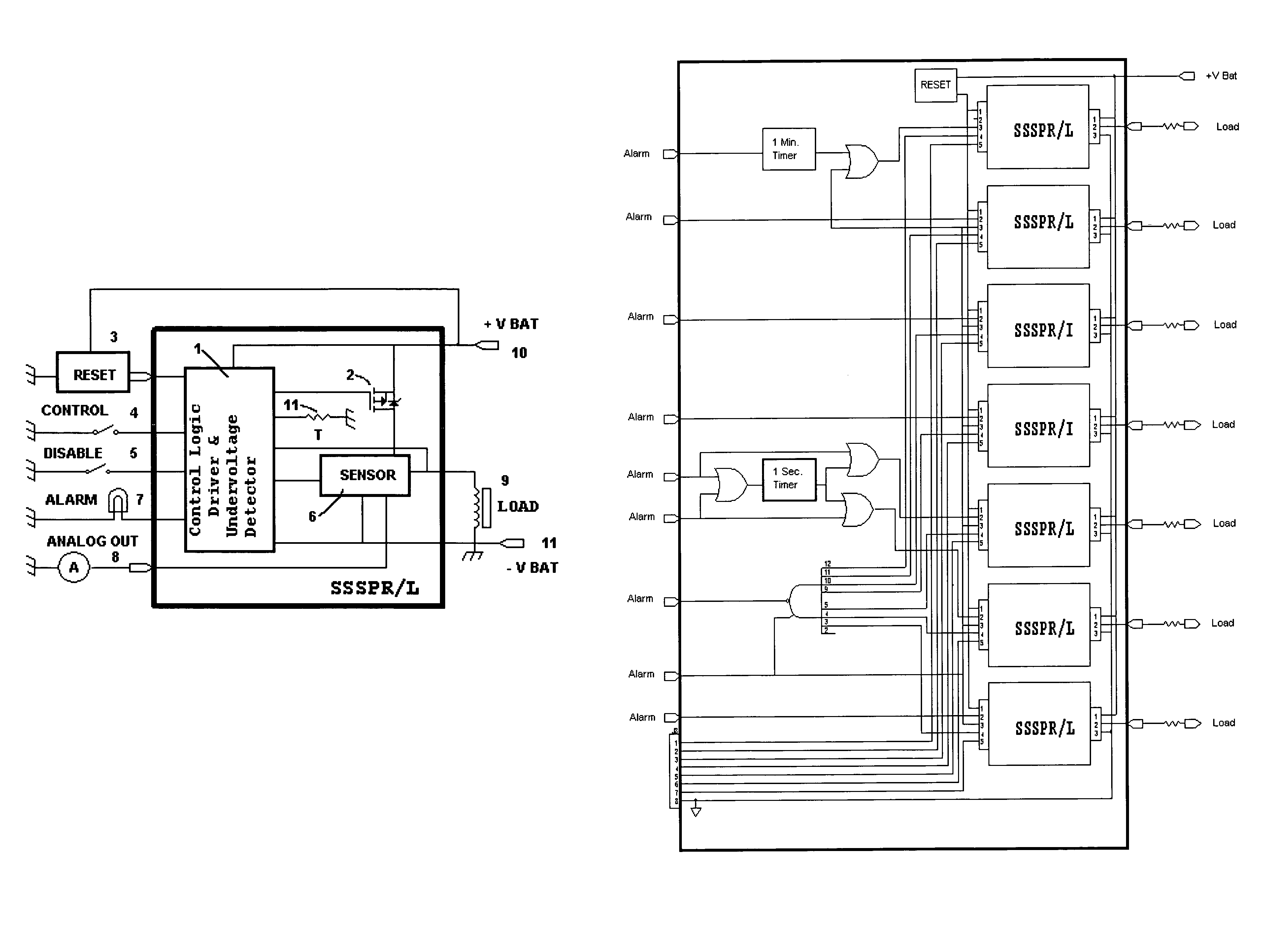
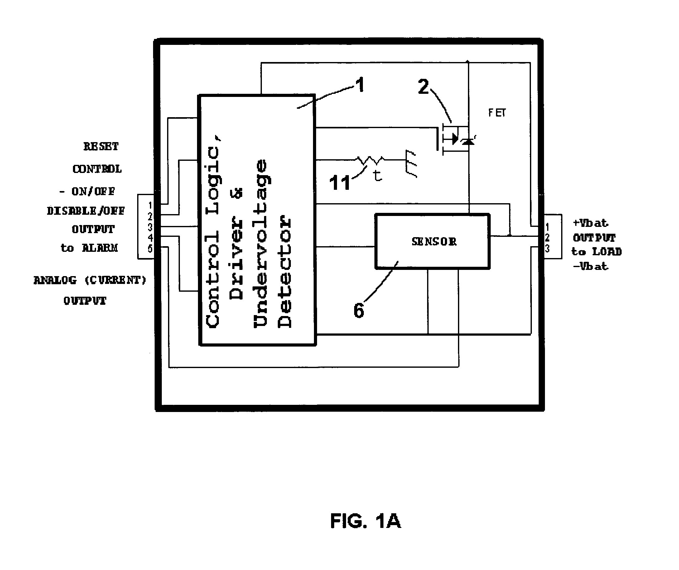
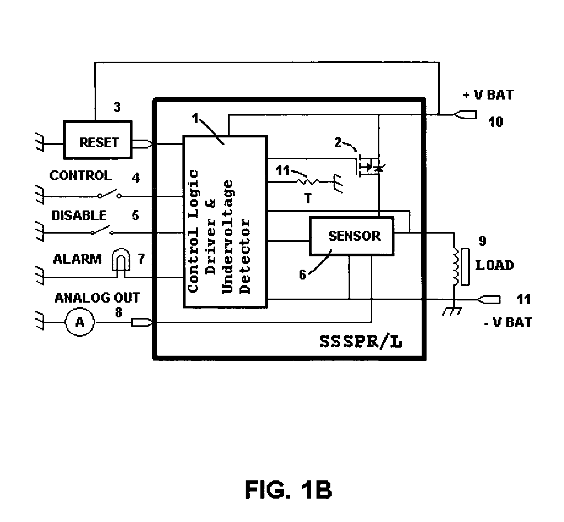
[0029]The power control module of the present invention is designed around several solid state self-protective relays (SSSPR), and embodiment of one of them is shown in FIG. 1A. The SSSPR consist of three major parts: a power MOSFET 2, a Hall-Effect or other current sensor with amplifiers 6, and a control logic 1. The control logic 1, processes various inputs and outputs such as reset, on / off, alarms, and possibly an analog current output. The sensor 6, is preferred to be a Hall-Effect sensor that can produce an output proportional to the magnetic field produced by the load current (or portion of the load current) flowing through it. This output can be fed back to the control logic 1 to provide over-current regulation and emergency shut-down. A thermal sensor 11 can directly sense the temperature of the MOSFET 2 and provide this information to the logic circuit 1. An over-temperature condition can cause a shutdown. The device of FIG. 1A can have an external reset, a disable control,...


PUM


Abstract

An intelligent, self-protected control module which is a fully protected and configured as a multi-terminal device controlling a number of power field-effect transistors for delivering power to loads. The device can contain a central processing unit or logic, precision Hall-Effect based current sensors for precise measuring of bypass currents, temperature sensors, and input/output circuitry as well as an optional RF receiver. The inputs can incorporate de-bouncing techniques to prevent false turn on/off. Inputs can provide command signals for the processor or logic with built-in watchdog circuitry to monitor the input power supply. The CPU or logic can provide communications with external devices, generate alarms, generate control signals to turn-on/turn-off power MOSFETs, and analyze currents and temperature of each channel. Unlike an electromechanical relay, the present invention is free from arcing and sparking, there are no contact materials to wear, and it is noiseless. The present invention provides over-current protection by shutting down a troubled channel if it is overloaded. It provides protection to the load by limiting the bypass current to the preset value, or shutting the channel off in a case of over-current. The present invention provides over-temperature protection by shutting down an appropriate channel if any of the MOSFET's temperature reaches a predetermined value. The present invention can generate an output signal that is capable of driving an external indicator lamp if a problem has occurred. An optional RF receiver designed to receive a coded signal from a key-chain transmitter can provide a method of enabling the module to accept a control signal from the input remotely.

Description

BACKGROUND[0001]1. Field of the Invention[0002]The present invention relates generally to electric power control and more specifically to self-protected, intelligent power control module. The present invention, in specific embodiments, can be used as a power control center for a vehicle such as a motorcycle, automobile, boat or airplane and many industrial and defense applications where protection of a load is essential.[0003]2. Description of the Prior Art[0004]For years, electromechanical relays have been used in a wide variety of power control and other electrical applications. These mechanical devices, which are built of a coil and contacts, have demonstrated considerable reliability; however, they suffer from numerous problems associated with having moving parts. In particular, mechanical relays are subject to arching and sparking. In applications where it is required to switch a high DC voltage, the cost of a mechanical relay grows very rapidly. The switching of the coil leads...

Claims


Application Information

Patent Timeline
Patent Type & Authority Patents(United States)
IPC IPC(8): H01H9/00
CPCH03K17/0822H02H3/087H03K2017/0806
Inventor SHVARTSMAN, VLADIMIR A.IVANYUK, YURIY
Owner SHVARTSMAN VLADIMIR
Why Eureka
Try Eureka