Reduced power differential type termination circuit

a termination circuit and differential type technology, applied in logic circuit coupling/interface arrangement, pulse technique, baseband system details, etc., can solve the problems of large dc current of 9 ma and other problems, and achieve the effect of reducing power consumption, maintaining or improving signal integrity and overall performan

Active Publication Date: 2010-07-06
INTEGRATED DEVICE TECH INC
View PDF5 Cites 26 Cited by
  • Summary
  • Abstract
  • Description
  • Claims
  • Application Information

AI Technical Summary

Benefits of technology

[0009]The reduced power differential type termination circuit, at least in some implementations relative to other termination circuits, may reduce power consumption while maintaining or improving signal integrity and overall performance.

Problems solved by technology

A DC current of 9 mA is considerable and problematic considering chips, subject to limitations on power consumption, may have many inputs with on-die terminations.

Method used


Image

  • Reduced power differential type termination circuit
  • Reduced power differential type termination circuit
  • Reduced power differential type termination circuit

Examples


Embodiment Construction

Of Illustrative Embodiments. This Summary is not intended to identify key or essential features of the claimed subject matter, nor limit the scope thereof.

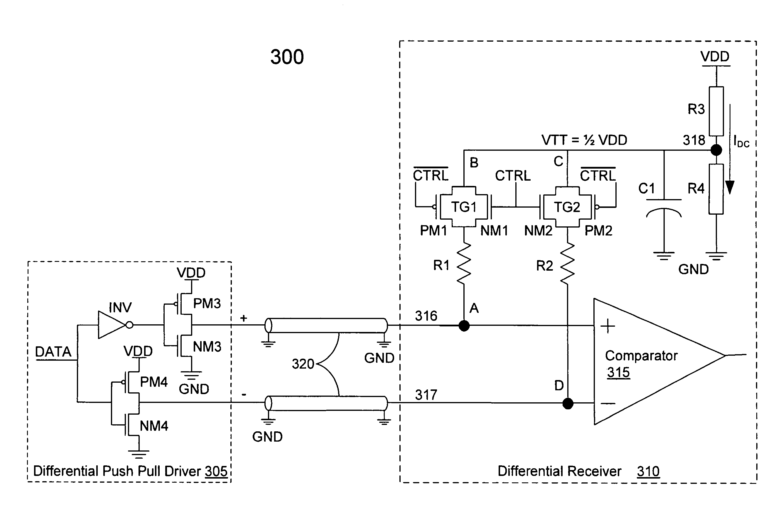
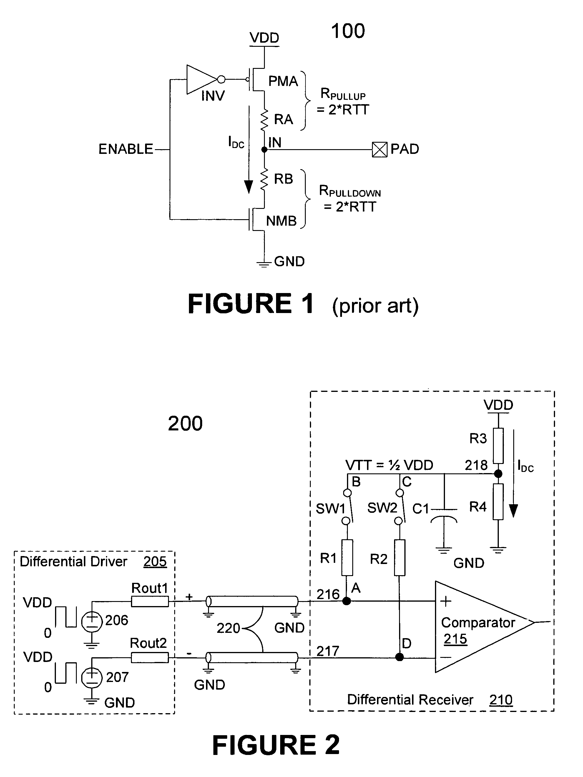
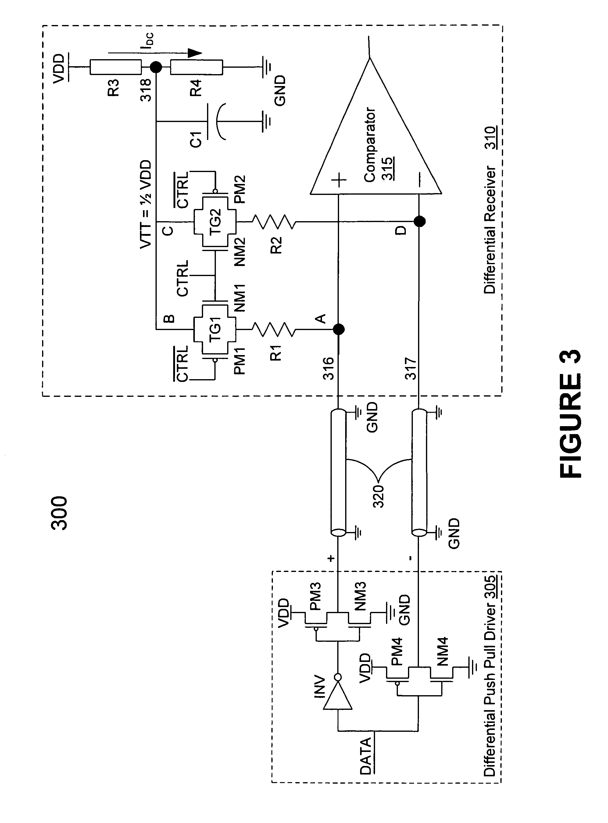
[0007]The present invention provides for a reduced power differential type termination circuit for use in stub series terminated logic (SSTL), high speed transceiver logic (HSTL) and other transmission line systems. A differential type termination circuit in accordance with some embodiments of the invention, whether implemented on or off die, stand-alone, in a receiver or in a transmission system may comprise, for example, first and second nodes for coupling, respectively, to first and second transmission lines; a first impedance coupled between the first transmission line and a third node; a second impedance coupled between the second transmission line and the third node; and a low direct current reference voltage generator for generating a reference voltage applied to the third node.

[0008]The first and second transmission lines ...


PUM


Abstract

A reduced power differential type termination circuit for use in SSTL, HSTL and other transmission line systems reduces power consumption. A differential type termination circuit may comprise first and second nodes for coupling, respectively, to first and second transmission lines; a first impedance coupled between the first transmission line and a third node; a second impedance coupled between the second transmission line and the third node; and a low direct current reference voltage generator for generating a reference voltage applied to the third node. The first and second transmission lines may transmit complimentary signals. The first and second impedances may be symmetric or asymmetric. The first impedance may match the second impedance. The first and second impedances may, respectively, match the impedances of the first and second transmission lines. The first and / or second impedances may include a bidirectional switch, such as a transmission gate, to enable and disable the termination circuit.

Description

TECHNICAL FIELD[0001]The present invention generally relates to termination circuits in the field of data transmission. More particularly, the invention relates to differential type termination circuits for terminating data transmission links.BACKGROUND[0002]FIG. 1 illustrates a well-known impedance matching circuit used to terminate data transmission links. Impedance-matching termination circuit 100 is generally implemented on-die (i.e. as an integrated circuit on a chip rather than as discrete components on a motherboard). Termination circuit 100 is used in single-ended and differential receivers on transmission lines for technologies such as high speed transceiver logic (HSTL) and stub series terminated logic (SSTL). Termination circuit 100 comprises PMOS transistor PMA, NMOS transistor NMB, resistors RA, RB and inverter INV coupled to input pad PAD. A signal is received at input node IN through input pad PAD. Input node IN is coupled to, for example, an input terminal of a compa...

Claims


Application Information

Patent Timeline
Patent Type & Authority Patents(United States)
IPC IPC(8): H03K17/16
CPCH03K19/0005H03K19/017545H04L25/0272H04L25/028H04L25/0292H04L25/0298H03K19/0008
Inventor ZHANG, YU MINWANG, SHOUJUN
Owner INTEGRATED DEVICE TECH INC
Why Eureka
Try Eureka