Instrument and method for tandem time-of-flight mass spectrometry

a mass spectrometry and tandem technology, applied in mass spectrometers, separation processes, separation of dispersed particles, etc., can solve problems such as difficult analysis, complicated spectrum, and increased instrument siz

Active Publication Date: 2010-07-13
JEOL LTD
View PDF11 Cites 33 Cited by
  • Summary
  • Abstract
  • Description
  • Claims
  • Application Information

AI Technical Summary

Problems solved by technology

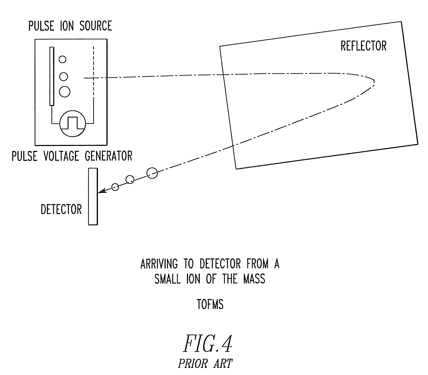
However, in the prior art linear TOFMS and reflectron TOFMS, prolongation of the total flight time T, i.e., increase of the total flight distance, will immediately result in an increase in size of the instrument.
However, the TOFMS in which ions are made to make multiple turns in a closed orbit suffers from an overtaking problem.
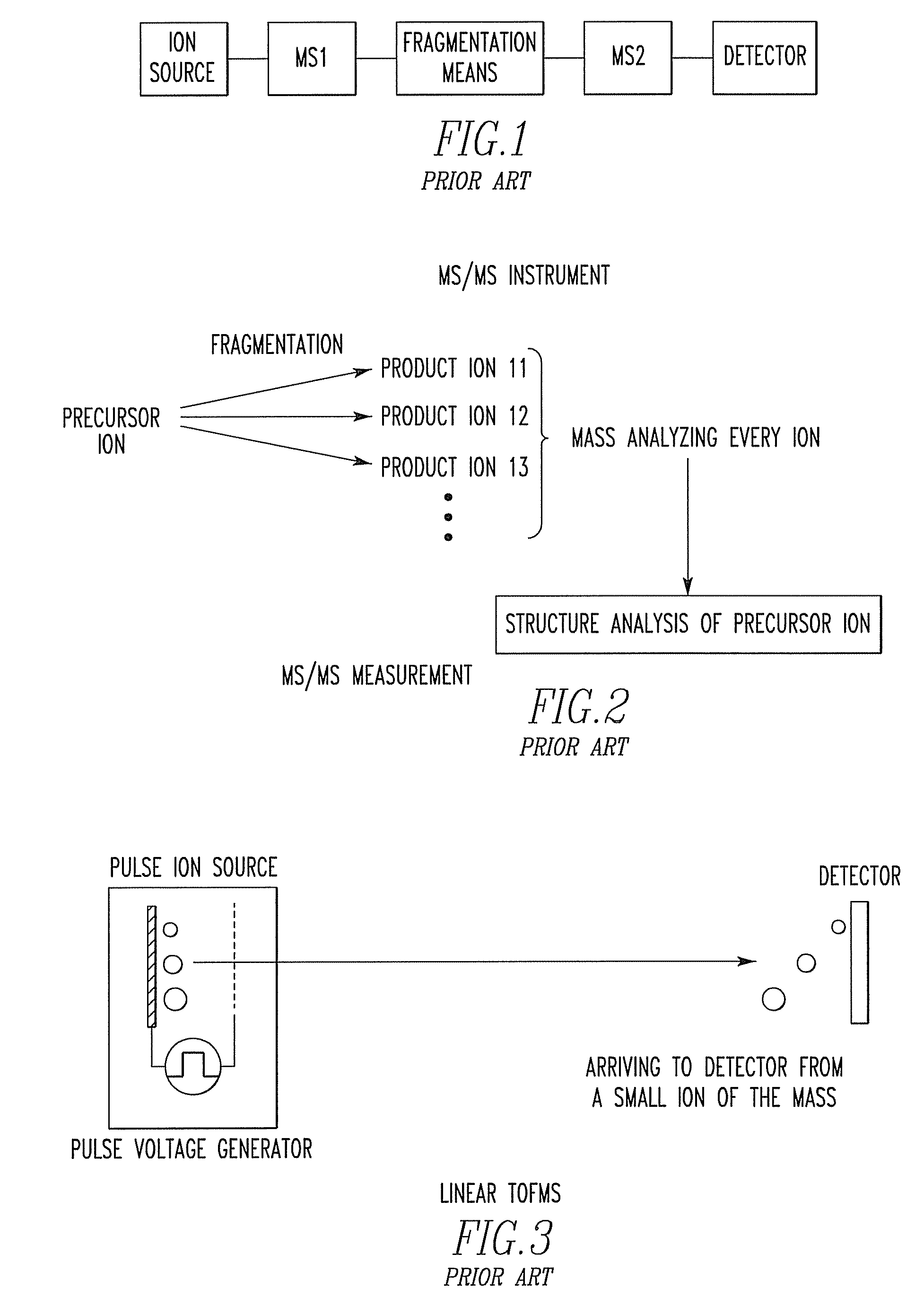
CON: 3: Since product ions produced by PSD fragmentation and product ions produced by CID fragmentation are mixed, the resulting spectrum is complicated and difficult to analyze.
This leads to wasteful consumption of the sample.
However, CONs 3 and 4 are the fundamental drawbacks with prior art TOF / TOF and, therefore, it is difficult to solve these drawbacks.
A first problem with the prior art is that the precursor ion selectivity is low.
That is, it is impossible to separate these ions however short the response time of the ion gate.
Consequently, the ions cannot be separated.
A second problem with the prior art is that the mass resolution and mass accuracy of MS2 are low.
However, with these methods, it is difficult to converge all the ions having a very wide range of kinetic energies.
Generally, MS / MS measurements result in poorer mass resolving power than MS measurements using reflectron TOFMS.
The resolving power is deteriorated due to the structure of TOF / TOF instrument.
However, where TOFMS instruments are connected in tandem, not all ions are identical in initial position because ions with different m / z are separated by TOF1 and because plural ions having different m / z values are introduced into the second TOFMS due to poor precursor ion selectivity.
Consequently, the mass resolution and mass accuracy of TOF2 are deteriorated.
A third problem with the related art is that the results of MS / MS measurement are complex.
Furthermore, in the prior art TOF / TOF instrument, TOF1 is a linear TOFMS and so it is impossible to separate PSD ions.
As a result, as pointed out in Problem 2, the MS / MS spectrum becomes very complex because of low resolution of MS2.
In consequence, it is difficult to analyze the spectrum.
A fourth problem with the prior art is that it is possible to measure the fragment pathway from only one precursor ion during one MS / MS measurement.
It has been effectively impossible to select plural precursor ions in one measurement.
That is, since all the ions excluding the selected precursor ions are eliminated, the sample is consumed wastefully.

Method used


Image

  • Instrument and method for tandem time-of-flight mass spectrometry
  • Instrument and method for tandem time-of-flight mass spectrometry
  • Instrument and method for tandem time-of-flight mass spectrometry

Examples


first embodiment

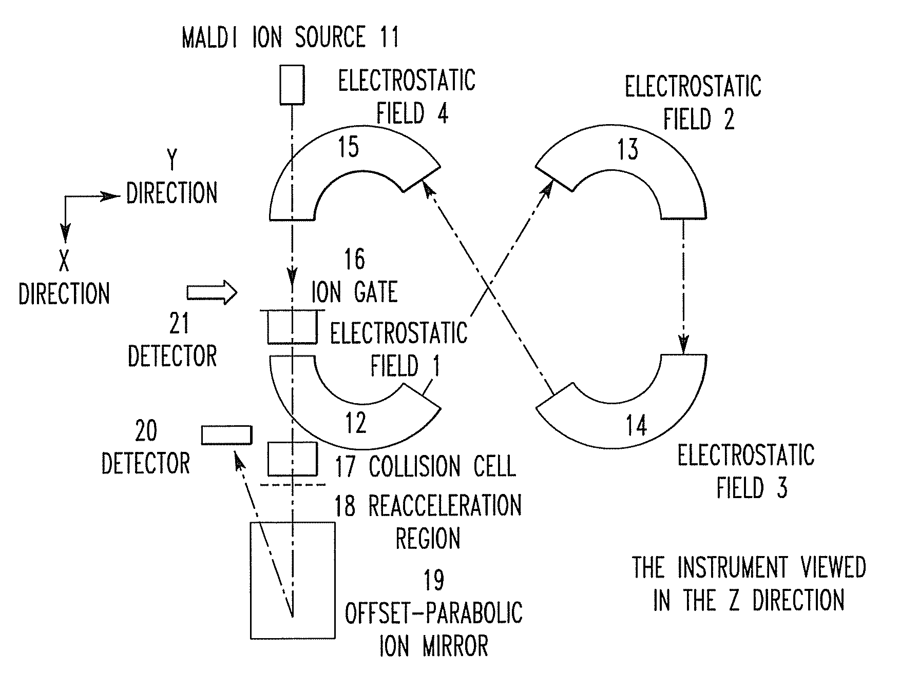
[0099]FIGS. 9A and 9B show a tandem time-of-flight mass spectrometer according to a first embodiment of the present invention. In FIG. 9A, the instrument is viewed in the Z-direction. In FIG. 9B, the instrument is viewed in the direction indicated by arrows (Y-direction) in FIG. 9A. The spectrometer has a MALDI ion source 11, electric sectors 12-15 stacked on top of each other in the Z-direction to form an 8-shaped spiral trajectory, an ion gate 16 for selecting precursor ions, a collision cell 17 for fragmenting ions, an ion reacceleration region 18 formed between a spiral trajectory TOF-MS (hereinafter may be referred to as the first TOF-MS) and reflectron TOF-MS (hereinafter may be referred to as the second TOF-MS) and using a constant voltage or a pulsed voltage, a reflectron field 19 into which ions fragmented in the collision cell 17 are admitted, and a detector 20 for detecting ions reflected by the reflectron field 19. In this embodiment, the reflectron field is formed by an...

second embodiment

[0109]The present embodiment is similar to the first embodiment except that a detector 21 for MS measurements is added as shown in FIGS. 12A and 12B. Normally, the diameters of ion exit and entrance ports in the collision cell 17 are about 1 mm to secure airtightness. Therefore, there is the possibility that detecting ions passed through the collision cell 17 in MS measurements is disadvantageous in terms of sensitivity. Furthermore, as described previously, the mass dependence of the mass resolution during MS measurements can be reduced by shortening the distance from the sample plate to the focal point used in delayed extraction. For these reasons, better data can be effectively obtained in both MS measurement and MS / MS measurement by varying the focal point used in delayed extraction.

[0110]First, the compounds of a sample are ionized in the MALDI ion source. The resulting ions are accelerated by delayed extraction. The ion optics of the first TOF-MS are so designed that spatial f...

third embodiment

[0114]The present embodiment is a partial modification of the second embodiment as shown in FIGS. 13A and 13B. In the present embodiment, an ion passage hole 22 is formed in an electric sector that is located upstream of the circular path where the detector 21 is disposed and downstream of the circular path where the ion gate 16 is disposed. The collision cell 17, reacceleration region 18, offset parabolic ion mirror 19, and detector 20 are disposed on a straight line that is an extension of the flight trajectory extending straight from the ion passage hole.

[0115]In the case of MS measurements, a voltage is applied to the electric sector having the ion passage hole 22. The ions are made to travel in the spiral trajectory without permitting the ions to pass through the passage hole 22. In the case of MS / MS measurements, the electric field produced by the electric sector needs to be eliminated to permit the ions selected by the ion gate 16 to pass through the ion passage hole 22. Wher...


PUM


Abstract

A novel instrument and method for TOF / TOF mass spectrometry is offered. A spiral trajectory time-of-flight mass spectrometer satisfies the spatial focusing conditions for the direction of flight and a direction orthogonal to the direction of flight whenever ions make a turn in the spiral trajectory. An ion gate for selecting precursor ions is placed in the spiral trajectory of the spiral trajectory time-of-flight mass spectrometer. Electric sectors are placed downstream of the ion gate.

Description

BACKGROUND OF THE INVENTION[0001]1. Field of the Invention[0002]The present invention relates to instrument and method for tandem time-of-flight mass spectrometry used for quantitative analysis and simultaneous qualitative analysis of trace amounts of compounds and used for structural analysis of sample ions.[0003]2. Description of Related Art[0004][Mass Spectrometers][0005]A mass spectrometer ionizes a sample in an ion source, separates the ions according to each value of m / z (mass-to-charge ratio) by the mass analyzer, and detects the separated ions by a detector. The result is shown in the form of a mass spectrum in which m / z value is plotted on the horizontal axis, while the relative amount is on the vertical axis. The m / z values and relative intensities of compounds contained in the sample are obtained. Qualitative and quantitative information of the sample can be derived. Various methods are available for ionization, mass separation, and ion detection. The present invention is...

Claims


Application Information

Patent Timeline
Patent Type & Authority Patents(United States)
IPC IPC(8): H01J49/00
CPCH01J49/004H01J49/408
Inventor SATOH, TAKAYA
Owner JEOL LTD
Why Eureka
Try Eureka