Method of manufacturing a flow rate sensor

a flow rate sensor and manufacturing method technology, applied in the direction of liquid/fluent solid measurement, instruments, conductive pattern formation, etc., can solve the problems of temperature variation, limited measurement technique, limited conventional technology of mass flow sensor, etc., and achieve the effect of expanding the dynamic measurement rang

Active Publication Date: 2010-08-03
M TECH INSTR HLDG
View PDF3 Cites 14 Cited by
  • Summary
  • Abstract
  • Description
  • Claims
  • Application Information

AI Technical Summary

Benefits of technology

[0016]According it is an object of the present invention to provide a MEMS mass flow sensor and MEMS flow sensor array with low heating power consumption and large measurable flow rate range. In addition, the present invention further discloses the methods for making the mass flow sensors.
[0017]According to the present invention, the reference resistor in a preferred embodiment is at least three-time larger than resistance of the heater. With increased resistance of the reference resistor, the power consumption by heater control circuit is cut down by 30%˜50%.
[0018]According to the present invention, a requirement to symmetrically arrange the upstream and downstream sensing elements with respect to the heater is removed. For each pair of upstream and downstream sensing elements, the distance between the upstream sensing element and the heater can be used as a design parameter independent to the distance between the downstream sensing element and the heater. The distance between the downstream sensing element and the heater is itself also a design parameter. This allows for more design flexibility to achieve larger range of measurable flow rates.
[0019]In accordance with the present invention, a small resistor physically placed in an ambient temperature environment is connected in series to the downstream sensing element within a same branch of the bridge sensing circuit. Such a small resistor is utilized to offset fabrication variation, and its value depends on fabrication quality. With this novel configuration, the bridge sensing circuit is able to sense extremely slow flows, which in turns increases the measurable flow rate range.

Problems solved by technology

Conventional technologies of mass flow sensors are still limited by the difficulties of limited ranges of flow rate measurement and the requirement to maintain a high level of heating power.
The stream of flow when passing over the mass flow sensor, carries away the heat from the heater thus causes temperature variations.
However, due to the variations and uncertainties of flow velocity, this measurement technique has limited accuracy when applied to measurements over a relative large range of flow rate measurement.
As a result, the pulse width tends to be too broad to be useful for measurement of slow flows and the flow rate measurement become inaccurate particularly for measuring flows below certain flow velocity.
The pulsed power techniques as discussed above still face the difficulties that the range of measurements and accuracy are limited.
However, the above-mentioned techniques as discussed do not provide a resolution to the major concerns for mass flow sensors.

Method used


Image

  • Method of manufacturing a flow rate sensor
  • Method of manufacturing a flow rate sensor
  • Method of manufacturing a flow rate sensor

Examples


Embodiment Construction

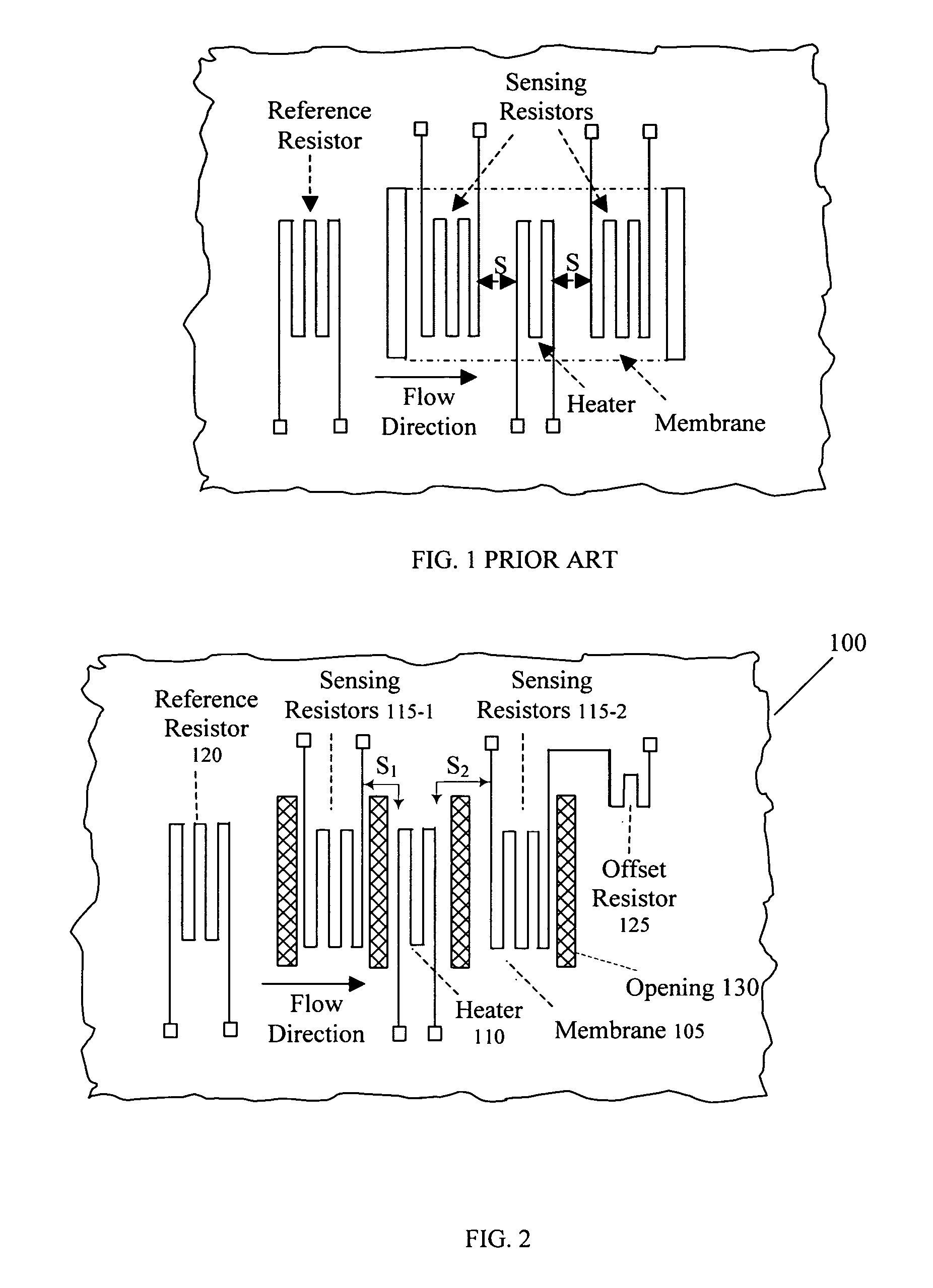
[0036]FIG. 2 shows a top view of a flow rate sensor 100 as a preferred embodiment of the present sensor. The flow rate sensor 100 is supported on a membrane 105 and is manufactured by applying the MEMS manufacturing processes as illustrated below. The flow rate sensor includes a heater 110 and temperature sensing resistors 115-1 and 115-2 disposed on the upstream and downstream of the heater 110. The upstream and downstream sensing resistors may be symmetrical, i.e., resistors of equal resistance, or non-symmetrical resistors, i.e., resistors of different resistances. The upstream and downstream sensing resistors may be arranged to locate at either a symmetrical or non-symmetrical locations. The flow rate sensor further includes a reference resistor 120 that is provided to have a resistance that is at least three times greater than the resistance of the heater 110. The purpose to provide a reference resistor 120 that has greater resistance is to minimize the power dissipation over t...


PUM

PropertyMeasurementUnit
angleaaaaaaaaaa
resistanceaaaaaaaaaa
velocitiesaaaaaaaaaa

Abstract

A mass flow sensor is manufactured by a process of carrying out a micro-machining process on an N or lightly doped P-type silicon substrate with orientation <100>. This mass flow sensor comprises a central thin-film heater and a pair of thin-film heat sensing elements, and a thermally isolated membrane for supporting the heater and the sensors out of contact with the substrate base. The mass flow sensor is arranged for integration on a same silicon substrate to form a one-dimensional or two-dimensional array in order to expand the dynamic measurement range. For each sensor, the thermally isolated membrane is formed by a process that includes a step of first depositing dielectric thin-film layers over the substrate and then performing a backside etching process on a bulk silicon with TMAH or KOH or carrying out a dry plasma etch until the bottom dielectric thin-film layer is exposed. Before backside etching the bulk silicon, rectangular openings are formed on the dielectric thin-film layers by applying a plasma etching to separate the area of heater and sensing elements from the rest of the membrane.

Description

[0001]This Application is a Divisional Application and claims a Priority Filing Date of Mar. 11, 2004 benefited from a previously filed application Ser. No. 10 / 799,071 now abandoned filed previously by the inventors of this patent application.BACKGROUND OF THE INVENTION[0002]1. Field of the Invention[0003]The present invention generally concerns mass flow sensors, and more particularly, concerns mass flow sensors made of micro-electromechanical systems (MEMS) approach, and methods of manufacturing such mass flow sensors.[0004]2. Description of the Related Art[0005]Conventional technologies of mass flow sensors are still limited by the difficulties of limited ranges of flow rate measurement and the requirement to maintain a high level of heating power. Specifically, the commercially available mass flow sensors are commonly made of transducers that include heaters and temperature sensors. The heater and temperature sensors are commonly provided with resistance wires such as platinum w...

Claims


Application Information

Patent Timeline
Patent Type & Authority Patents(United States)
IPC IPC(8): H05B3/00
CPCG01F1/6845Y10T29/49083Y10T29/49124Y10T29/49155Y10T29/49117Y10T29/49082
Inventor YAO, YAHONGCHEN, CHIH-CHANGWANG, GAFENGHUANG, LIJI
Owner M TECH INSTR HLDG
Why Eureka
Try Eureka