Diode and display device including diode
a display device and diode technology, applied in the direction of diodes, semiconductor devices, instruments, etc., can solve the problems of increasing cost, reducing yield, and reducing the operation of polycrystalline semiconductor films, so as to achieve high field effect mobility, reduce the off current of thin film transistors, and reduce the effect of yield
- Summary
- Abstract
- Description
- Claims
- Application Information
AI Technical Summary
Benefits of technology
Problems solved by technology
Method used
Image
Examples
embodiment mode 1
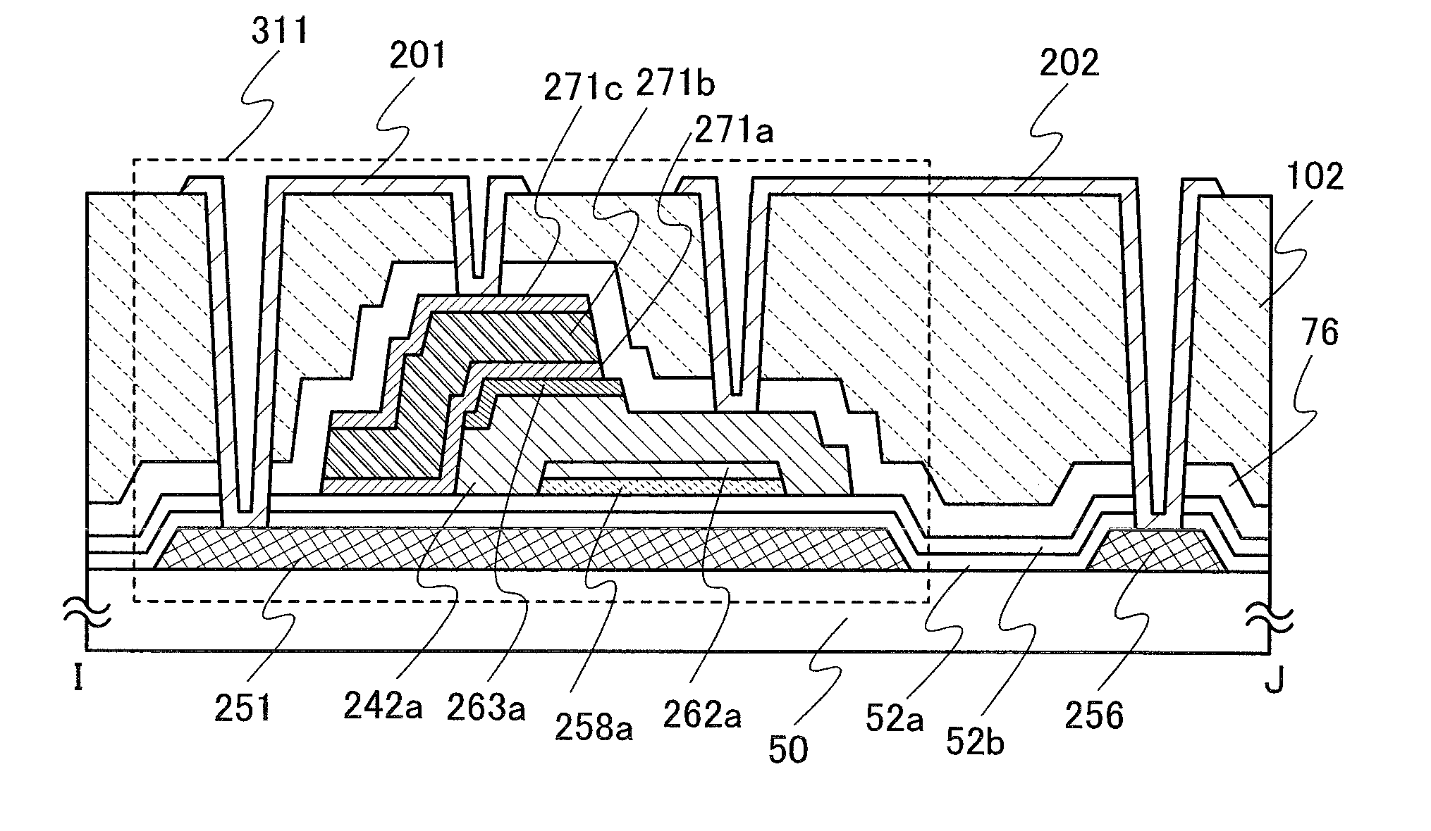
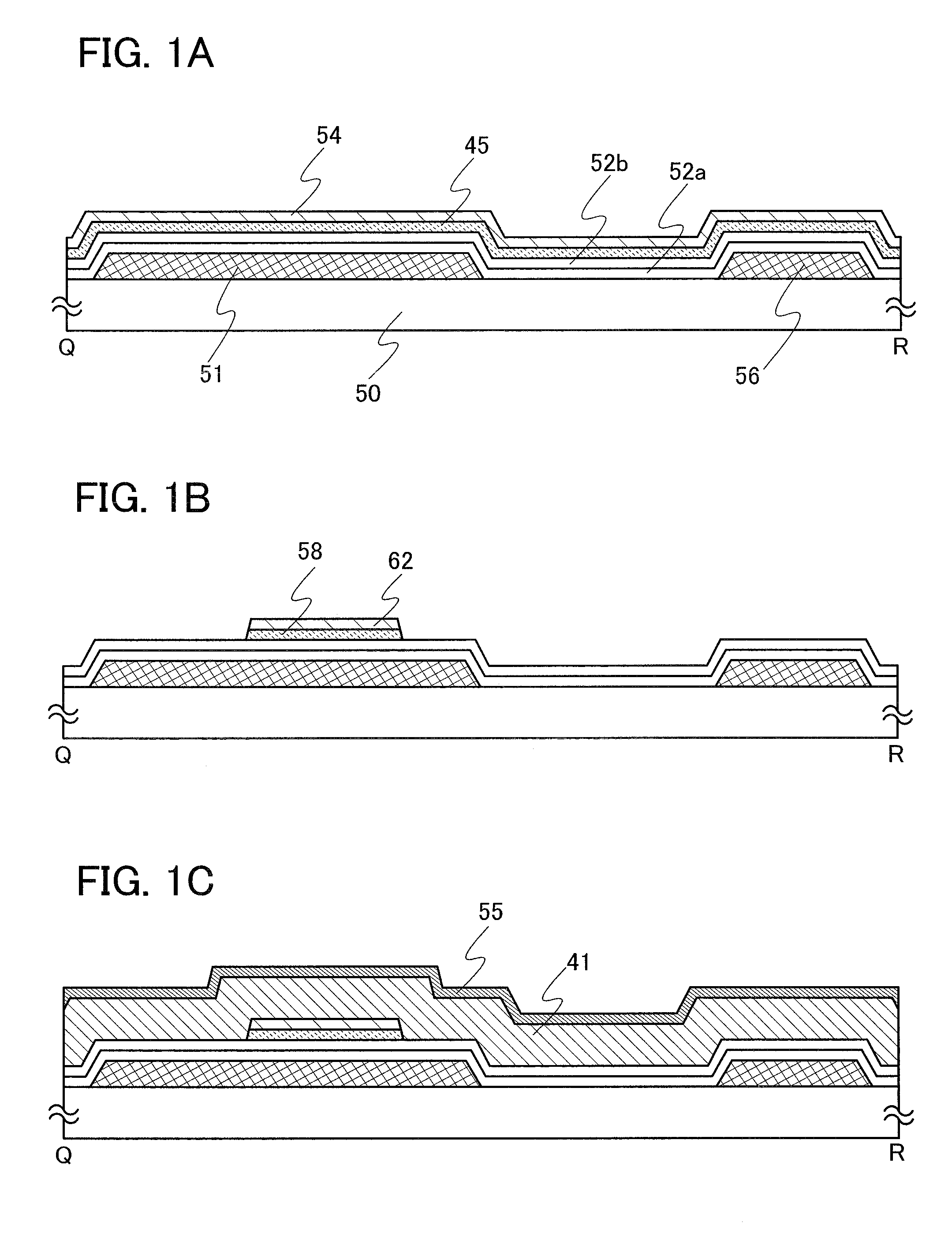
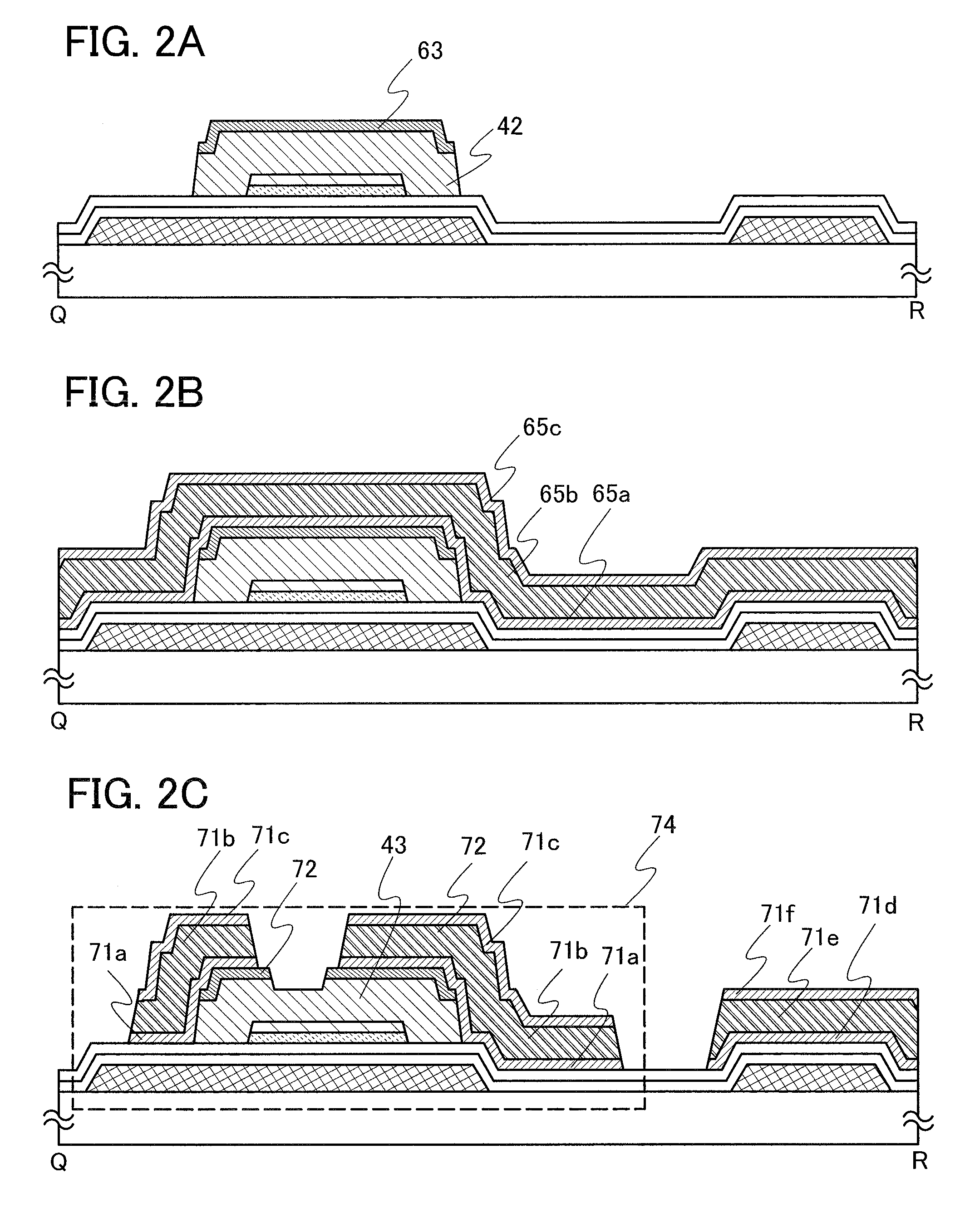
[0058]In this embodiment mode, a manufacturing process of a thin film transistor with high mobility, a large amount of on current, and a small amount of off current is described below. In this embodiment mode, manufacturing processes of a thin film transistor, a pixel electrode, and a capacitor element which are formed in each pixel of a pixel portion 1331 in the top view of an element substrate 1300 of a display device illustrated in FIG. 14 are described below.
[0059]Enlarged views of a region connected to a thin film transistor and a pixel electrode of one pixel of the pixel portion 1331 in FIG. 14 are illustrated in FIGS. 5A to 5D, cross-sectional views taken along a line Q-R in FIGS. 5A to 5D are illustrated in FIGS. 1A to 1C, FIGS. 2A to 2C, and FIGS. 3A to 3C, and cross-sectional views taken along a line S-T in FIGS. 5A to 5D are illustrated in FIGS. 4A to 4C.
[0060]As illustrated in FIG. 1A, a gate electrode 51 and a capacitor wiring 56 are formed over a substrate 50, and gate...
embodiment mode 2
[0120]In this embodiment mode, a process for manufacturing a thin film transistor using a process capable of reducing the number of photomasks compared with Embodiment Mode 1 is described.
[0121]In a similar manner to Embodiment Mode 1, as illustrated in FIG. 6A, a conductive film is formed over the substrate 50, a resist is applied over the conductive film, and the conductive film is partly etched using a resist mask formed through a photolithography process using the first photomask, so that the gate electrode 51 and the capacitor wiring 56 are formed. Subsequently, the gate insulating films 52a and 52b are formed over the gate electrode 51. Then, the microcrystalline semiconductor film 58 which includes the impurity element serving as a donor and the first buffer layer 62 are formed over the gate insulating film 52 through a photolithography process using the second photomask. Next, the second buffer layer 41, the impurity semiconductor film 55 to which the impurity element impart...
embodiment mode 3
[0145]In this embodiment mode, a mode which is different from the thin film transistors in Embodiment Modes 1 and 2 is described.
[0146]FIG. 10 illustrates a mode of thin film transistor in which crystal grains 60 which include an impurity element serving as a donor are dispersed over the gate insulating film 52b, and the crystal grains 60 which include the impurity element serving as a donor and a semiconductor film 61 which covers the crystal grains 60 which include the impurity element serving as a donor and the gate insulating film 52b and contains germanium as its main component are included instead of the microcrystalline semiconductor film which includes the impurity element serving as a donor of the thin film transistors shown in Embodiment Modes 1 and 2. In addition, the second buffer layer 43 which covers top and side surfaces of the semiconductor film 61 which contains germanium as its main component is formed. Compared with the crystal grains 60 which contains silicon as ...
PUM
 Abstract
Description
Claims
Application Information
 - R&D
- Intellectual Property
- Life Sciences
- Materials
- Tech Scout
- Unparalleled Data Quality
- Higher Quality Content
- 60% Fewer Hallucinations
Browse by: Latest US Patents, China's latest patents, Technical Efficacy Thesaurus, Application Domain, Technology Topic, Popular Technical Reports.
© 2025 PatSnap. All rights reserved.Legal|Privacy policy|Modern Slavery Act Transparency Statement|Sitemap|About US| Contact US: help@patsnap.com


