
Bezel packaging of frit-sealed OLED devices

a technology of fritsealed oled and packaging, which is applied in the directions of transportation and packaging, electroluminescent light sources, and semiconductor/solid-state device details, etc., can solve the problems that the improvement of structural integrity and the inability to protect the structural integrity of the glass assembly cannot improve the hermetic seal, so as to achieve the effect of reducing the potential for failur

Inactive Publication Date: 2010-08-31
CORNING INC
View PDF17 Cites 7 Cited by
  • Summary
  • Abstract
  • Description
  • Claims
  • Application Information

AI Technical Summary

Benefits of technology

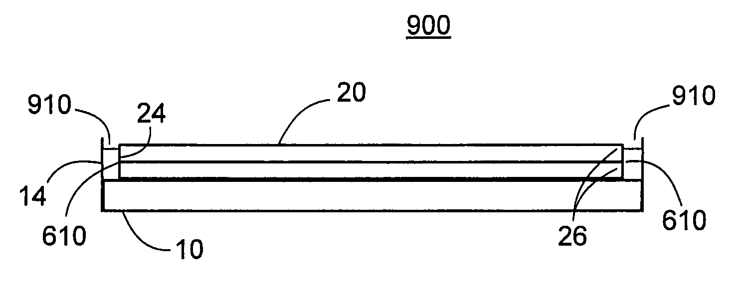
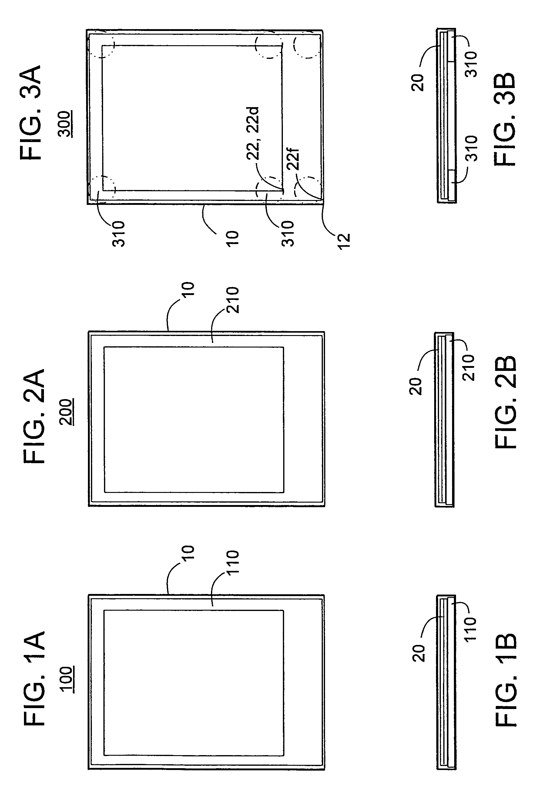
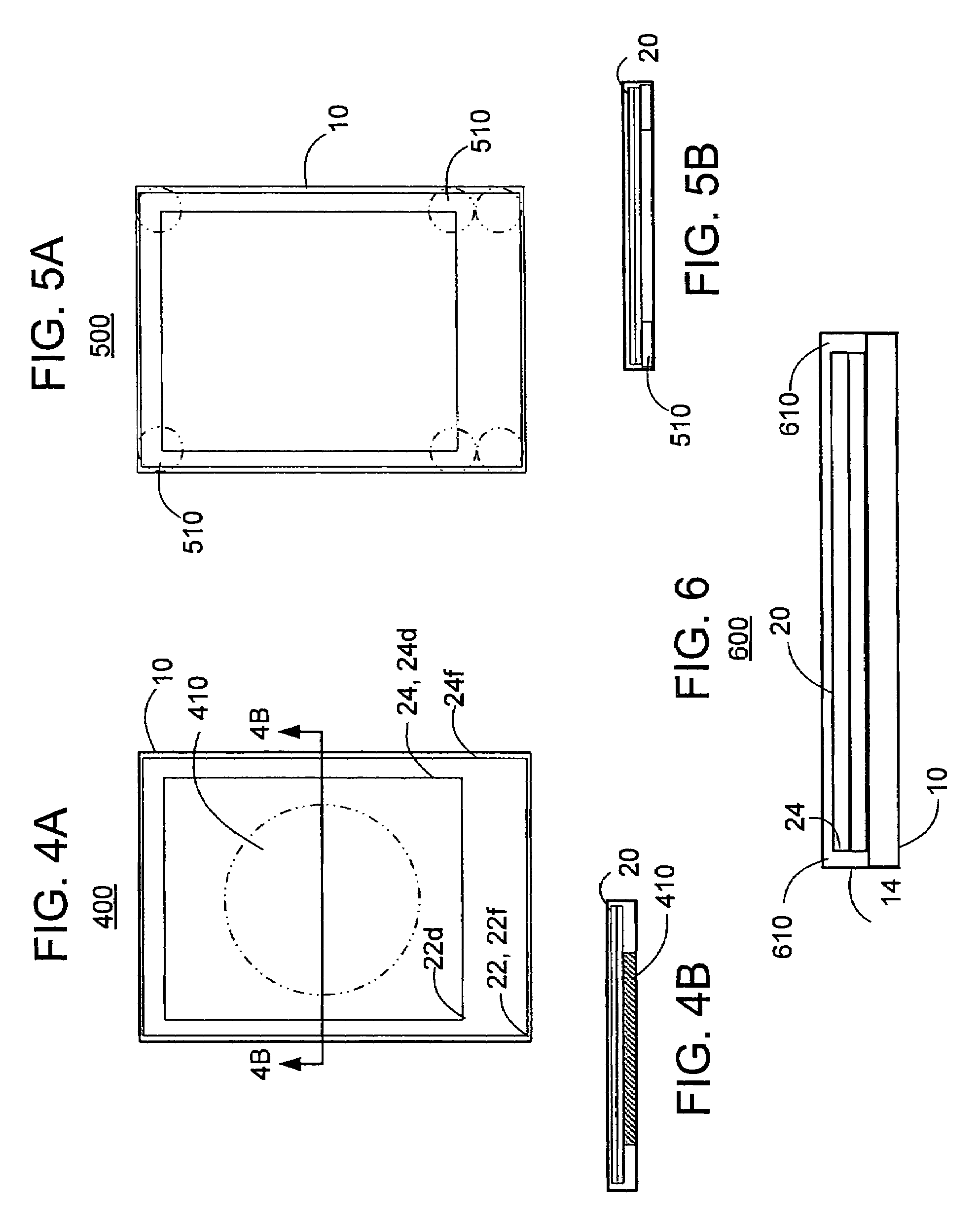
The present invention is about improving the mechanical reliability of sealed glass assemblies, such as OLED-frit sealed devices, by mitigating impact-induced high stresses that can lead to cracking and delamination of the sealed glass assembly. This is achieved by re-designing the bezel and packaging that holds the sealed display assembly, using low-modulus of elasticity compliant shock / impact absorbing material for the bezel. The invention also includes methods and apparatus for applying a bonding agent between the sealed glass assembly and the bezel, and making bezel modifications to stabilize the bezel. The advantages of the invention include improved mechanical integrity and reliability of the sealed devices, reduced localized bending and contact stresses at certain areas, and enhanced mechanical bonding between glass plates of a glass assembly.

Problems solved by technology

Producing flat product glass assemblies for OLED displays involves many challenges.
However, as technological advances are rarely synchronized, improvements in hermetic sealing may not protect the structural integrity of the glass assembly, and improvements in protecting the structural integrity may not improve the hermetic seal.

Method used


Image

  • Bezel packaging of frit-sealed OLED devices
  • Bezel packaging of frit-sealed OLED devices
  • Bezel packaging of frit-sealed OLED devices

Examples


Embodiment Construction

[0027]As an example of a sealed glass assembly, a hermetically sealed OLED glass assembly is manufactured by providing a first substrate glass plate and a second substrate glass plate, depositing organic light emitting diodes on the first substrate glass plate, and sealing the first and second glass substrates. After being sealed, such as with an epoxy, the glass assembly typically is inserted into a bezel, and a layer of adhesive tape typically is placed between the glass assembly and the bezel to hold the sealed glass assembly firmly into the bezel.

[0028]By way of example, the product glass may comprise CORNING INCORPORATED GLASS COMPOSITION Code 1737 or CORNING INCORPORATED GLASS COMPOSITION Code EAGLE2000™. These glass materials have numerous uses, in particular, for example, the production of displays, also including liquid crystal displays.

[0029]Organic light emitting diodes have been the subject of a considerable amount of research in recent years because of their use and pot...


PUM

PropertyMeasurementUnit
elastic modulusaaaaaaaaaa
modulus of elasticityaaaaaaaaaa
modulusaaaaaaaaaa

Abstract

Methods and assemblies relate to bezel packaging of a sealed glass assembly, such as a frit-sealed OLED device. The bezel packaging includes a shock absorbent intermediate layer of low modulus of elasticity material applied between the sealed glass assembly and the bezel. A bonding agent, which may include the low modulus of elasticity material and / or a separate bonding material, affixes the sealed glass assembly to the bezel. Bezel modifications may be made to stabilize the bezel. Exemplary bezel modifications include reinforced bezel side walls and supporting straps attached between bezel walls. The bezel design may include a gap between the edges of the sealed glass assembly and the bezel walls, so as to avoid direct contact therewith. The gap may be filled at least in part with low modulus of elasticity organic adhesive to provide additional shock absorbency. The low modulus of elasticity material may include foam, ceramic fiber cloth and / or a low modulus of elasticity polymeric organic coating.

Description

BACKGROUND[0001]1. Field of Invention[0002]The present invention relates to methods and apparatus relating to bezel packaging of a sealed glass assembly, such as for use in an organic light emitting diode (OLED) display, and in particular to bezel packaging of frit-sealed OLED devices.[0003]2. Description of Related Art[0004]Producing flat product glass assemblies for OLED displays involves many challenges. A key requirement in this process is the ability to package the displays in such as manner as to balance cost, performance, stability and durability. Displays based on organic light emitting diode (OLED) technology are sensitive to many factors, such as to the diffusion of oxygen and moisture into the OLED display, on the one hand, and to mechanical shock, on the other hand.[0005]To protect against the chemically based sensitivity factors, manufacturers typically attempt to hermetically seal OLED glass assemblies as best as manufacturing parameters permit. To protect against the ...

Claims


Application Information

Patent Timeline
Patent Type & Authority Patents(United States)
IPC IPC(8): H01L21/00
CPCB65D81/05C03C27/048H01L51/5237H10K59/873H10K59/871H05B33/04H10K50/84
Inventor BAYNE, JOHN FWESTBROOK, JAMIE TWIDJAJA, SUJANTO
Owner CORNING INC
Learn More