
Method and materials for patterning a neutral surface

a neutral surface and material technology, applied in the direction of photosensitive materials, instruments, photomechanical equipment, etc., can solve the problems of increasing the probability of unwanted signal propagation, process suffers from additional complexity, and the product of rc in the chip is reduced, so as to enhance the properties of the diblock copolymer

Active Publication Date: 2010-09-07
GLOBALFOUNDRIES US INC
View PDF23 Cites 40 Cited by
  • Summary
  • Abstract
  • Description
  • Claims
  • Application Information

AI Technical Summary

Benefits of technology

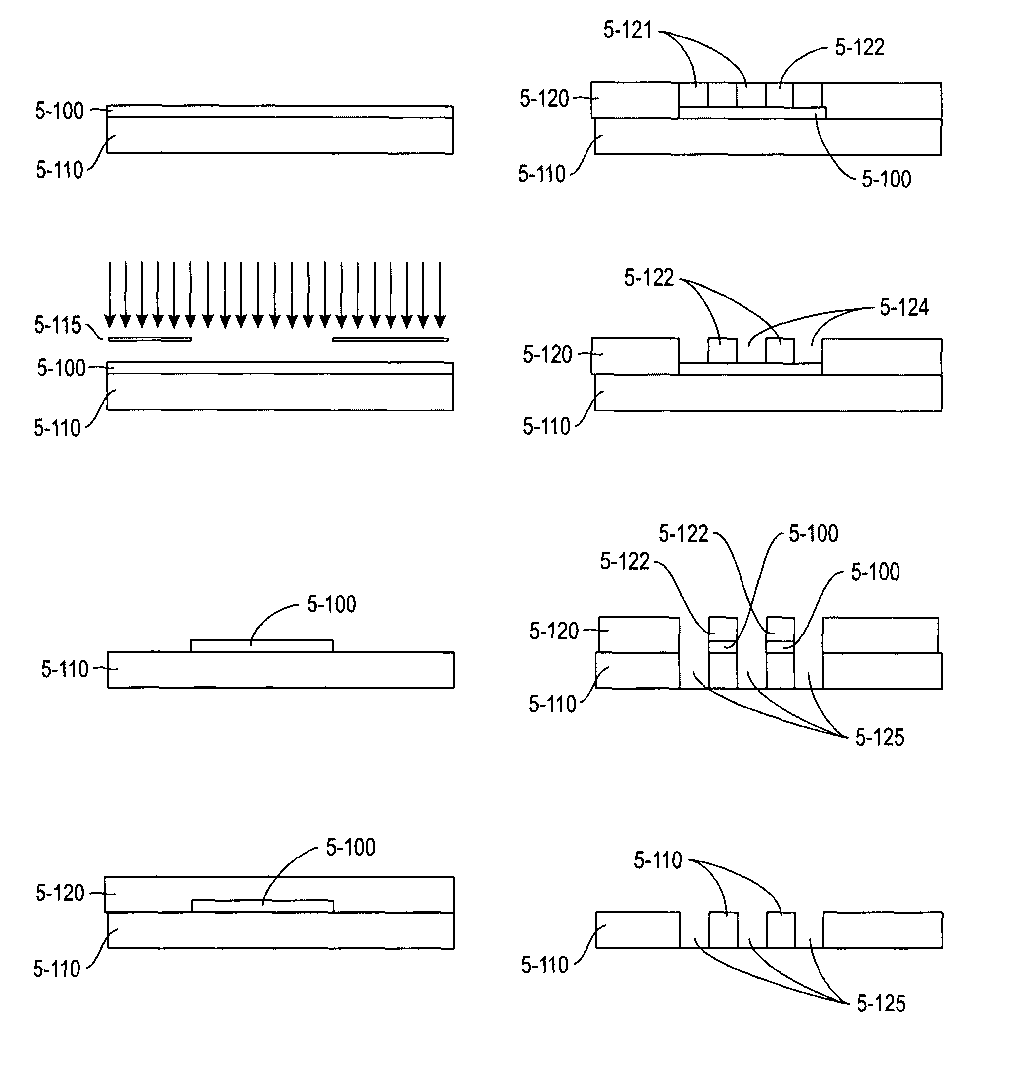
The present invention provides a method for combining a self-assembled structure and deterministic photolithography to create electronic components. The invention involves using a diblock copolymer film supported on a random copolymer film substrate. The surface energy of the random copolymer film substrate is tailored using a photolithographic process prior to the self-assembly step. The invention also includes a process for making a patterned neutral surface that can deter the formation of domains. The technical effects of this invention include precise control over domain formation, simplified processing, and improved properties of the electronic components.

Problems solved by technology

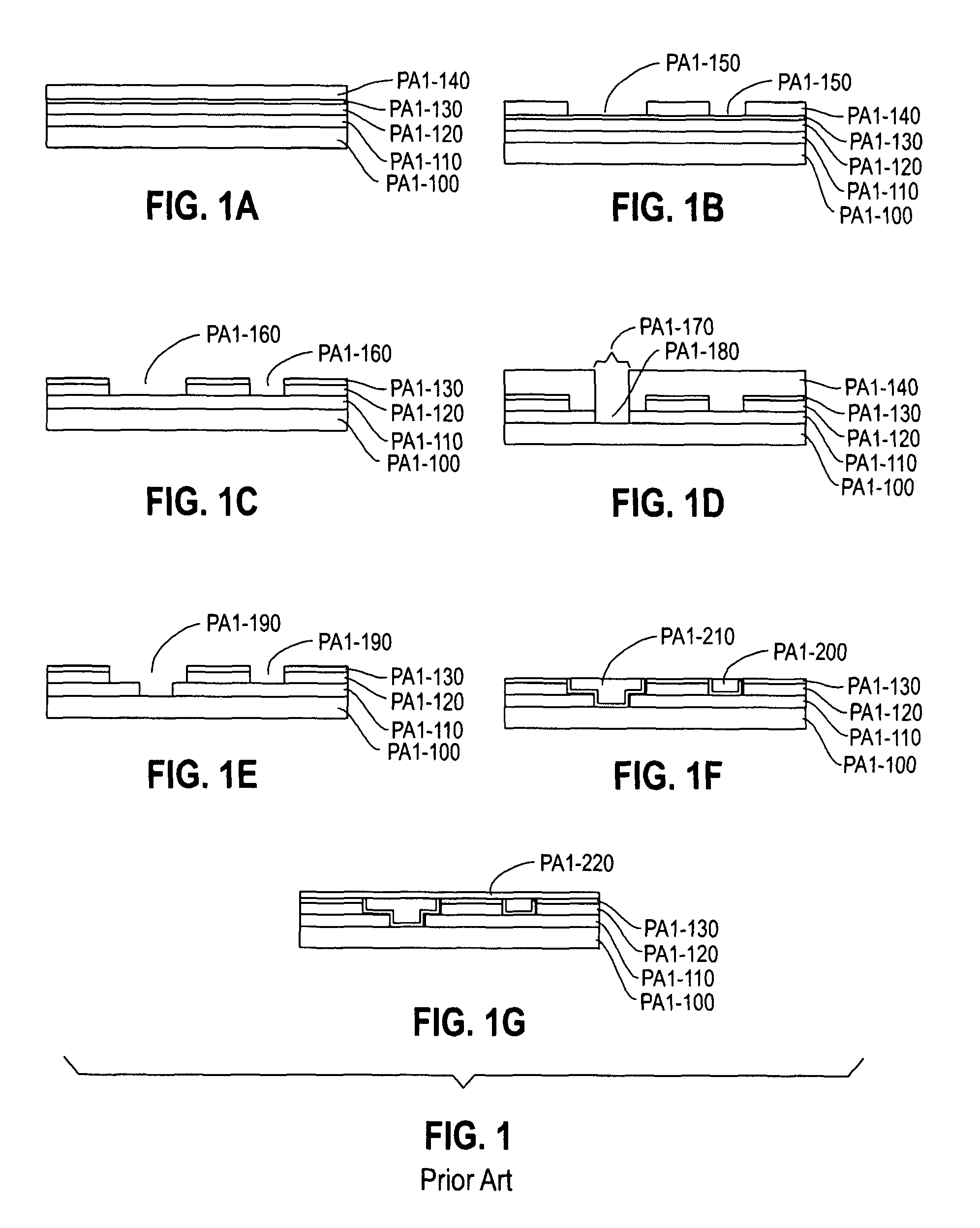
Manufacturers, in order to improve the performance of semiconductor chips, however, have reduced the resistivity (R) of the interconnector wires by replacing aluminum wiring with copper, and have also moved to lower dielectric constant (k) materials for the ILD, resulting in a reduction of the capacitance, C. In any event, the reduction of R or C or both results in a reduction of the product of R×C in the chip, thereby increasing the likelihood of unwanted signal propagation.
This process suffers from the additional complexity, processing steps, material, and equipment introduced into the conventional process steps in order to obtain the results from a blockout procedure.

Method used


Image

  • Method and materials for patterning a neutral surface
  • Method and materials for patterning a neutral surface
  • Method and materials for patterning a neutral surface

Examples


Embodiment Construction

[0001]1. Field of the Invention

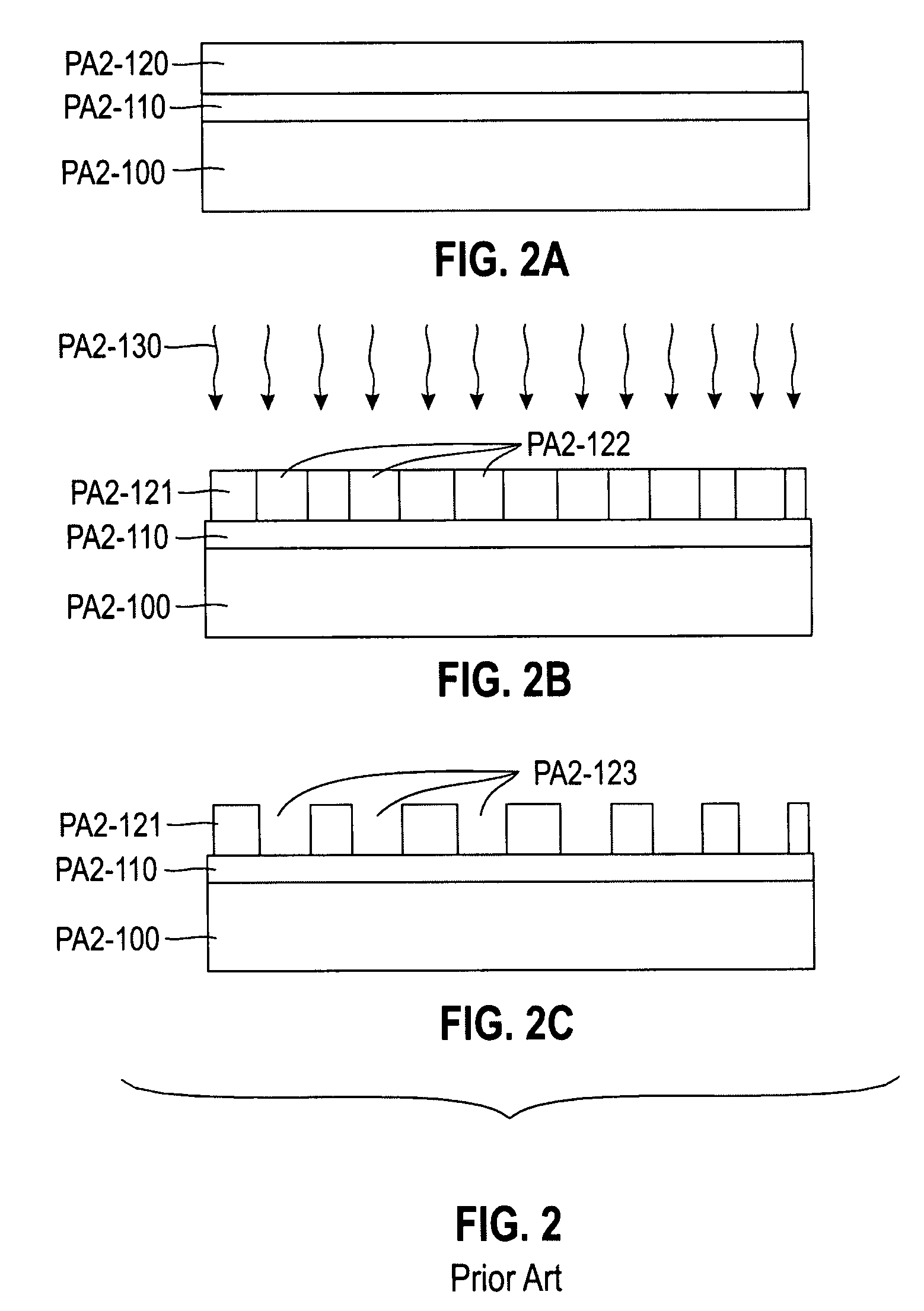
[0002]The field of the invention comprises convolved self-assembled structures such as nanostructures, and the fabrication of such structures by processes such as deterministic patterning processing methods, e.g., deterministic photolithography, which comprises the use of a master, such as a photolithographic mask to direct self-assembly in a predetermined location. Ion beam etching and other etch techniques known in the art can also be employed.

[0003]More specifically, and in one aspect, the fabrication comprises the generation of nanostructures by photolithography to pre-define regions in the structure where self assembly takes place.

[0004]2. Background of the Invention

[0005]The advancement of semiconductor computational speed has largely been driven by the ever smaller dimensions of semiconductor transistors and other integrated circuit (IC) components brought about by scaling their dimensions and / or properties.

[0006]Most of these processes rely on ...


PUM

PropertyMeasurementUnit
polymeric self assemblyaaaaaaaaaa
polarityaaaaaaaaaa
surface energyaaaaaaaaaa

Abstract

A self assembly step for the manufacture of an electronic component comprising, e.g., a semiconductor chip or semiconductor array or wafer comprises forming a block copolymer film placed on a random copolymer film substrate operatively associated with the electronic component and the block copolymer film wherein the surface energy of the random copolymer film is tailored by use of a photolithographic or chemical process prior to the self assembly step. By prior deterministic control over regional surface properties of the random copolymer film, domains of the block copolymer film form only in predefined areas. This approach offers simplified processing and a precise control of regions where domain formation occurs. Selective removal of some of the domains allows for further processing of the electronic component.

Description

DESCRIPTION OF THE INVENTION[0001]1. Field of the Invention[0002]The field of the invention comprises convolved self-assembled structures such as nanostructures, and the fabrication of such structures by processes such as deterministic patterning processing methods, e.g., deterministic photolithography, which comprises the use of a master, such as a photolithographic mask to direct self-assembly in a predetermined location. Ion beam etching and other etch techniques known in the art can also be employed.[0003]More specifically, and in one aspect, the fabrication comprises the generation of nanostructures by photolithography to pre-define regions in the structure where self assembly takes place.[0004]2. Background of the Invention[0005]The advancement of semiconductor computational speed has largely been driven by the ever smaller dimensions of semiconductor transistors and other integrated circuit (IC) components brought about by scaling their dimensions and / or properties.[0006]Most...

Claims


Application Information

Patent Timeline
Patent Type & Authority Patents(United States)
IPC IPC(8): G03F7/00G03F7/004
CPCB82Y10/00H01L21/31144H01L21/7682
Inventor BREYTA, GREGORYCOLBURN, MATTHEW E.
Owner GLOBALFOUNDRIES US INC
Learn More