Particulate material applicator and pump

a technology of powder applicator and pump, which is applied in the direction of lighting and heating apparatus, combustion types, coatings, etc., can solve the problems of difficult cleaning, difficult cleaning, and difficult application of dry particulate materials, so as to reduce the quantity of powder overspray, improve the cleaning effect, and reduce the time of color change

Inactive Publication Date: 2010-09-14
NORDSON CORP
View PDF60 Cites 19 Cited by
  • Summary
  • Abstract
  • Description
  • Claims
  • Application Information

AI Technical Summary

Benefits of technology

[0012]The invention provides apparatus and methods for improving the cleanability and reducing color change time for a material application system. Cleanability refers, among other things, to reducing the quantity of powder overspray that needs to be removed from exterior surfaces of the applicator and internal surfaces of the spray booth, and therefore is also related to the transfer efficiency. Cleanability also can refer to reducing the quantity of powder that needs to be purged or otherwise removed from interior surfaces that define the powder path from the supply through the spray applicator outlet. Cleanability can also refer to the ease with which the powder flow path can be purged or otherwise cleaned. Improving cleanability results in faster color change times by reducing contamination risk and shortening the amount of time needed to remove a first color powder from the powder flow path prior to introducing a second color powder.
[0013]In accordance with one aspect of the invention, cleanability is improved by providing improved transfer efficiency. By transfer efficiency is meant the percentage or ratio of sprayed powder that adheres to the target object to the total powder sprayed. In one embodiment, transfer efficiency is improved by a nozzle design that produces a slow moving dense phase cloud of powder. In one embodiment, a nozzle is provided that includes an expansion chamber to slow the powder flow exiting the nozzle. In a more particular embodiment, the cross-sectional area of the outlet orifice is greater than the cross-sectional area of the delivery hose connected to the nozzle. Air assist within the nozzle may optionally be provided for atomization and / or to produce a penetrating velocity. For electrostatic applicators, an electrode is provided that charges the cloud of powder on axis but with which the electrode and electrode holder are not disposed in the powder flow path. Other optional features in other embodiments include air wash of the electrode and a filter arrangement to prevent back flow of powder into the air passages used for air assist within the nozzle. An additional optional feature includes an integral deflector as part of the nozzle body.
[0016]In further accordance with this aspect of the invention, interior surface areas are reduced by designing the spray applicator to operate with high density low volume powder feed. In this context, high density means that the powder fed to the spray applicator has a substantially reduced amount of entrainment or flow air in the powder as compared to conventional powder flow systems. Low volume simply refers to the use of less volume of flow air needed to feed the powder due to its higher density as compared to conventional powder spray guns. By removing a substantial amount of the air in the powder flow, the associated conduits, such as a powder feed hose and a powder feed tube, can be substantially reduced in diameter, thereby substantially reducing the interior surface area. This also results in an significant reduction in the overall size of the spray applicator, thus further reducing the amount of exterior surface area exposed to powder overspray. For manually operated spray applicators, the invention provides an easily replaceable or removable powder path. In any case, a powder flow path is realized that optionally comprises only a single part.

Problems solved by technology

The application of dry particulate material is especially challenging on a number of different levels.
Wear items that have surfaces exposed to material impact, for example a spray nozzle in a typical powder spray gun, can be difficult to clean due to impact fusion of the powder on the wear surfaces.
Such systems are difficult to clean for a color change operation because the venturi pumps cannot be reverse purged, the suction tubes and associated support frames retain powder and changing the hoppers can be time consuming.
The sieve is also challenging and time consuming to clean as it often is in a separate housing structure as part of the powder recovery system or is otherwise not easily accessible.
Every minute that operators have to spend cleaning and purging the system for color change represents downtime for the system and inefficiency.
In order to achieve adequate powder flow rates (in pounds per minute or pounds per hour for example), the components that make up the flow path must be large enough to accommodate the flow with such a high air to material ratio (in other words lean flow) otherwise significant back pressure and other deleterious effects can occur.
The overall pump, however, in some cases may be less than optimal for purging, cleaning, color change, maintenance and material flow rate control.

Method used


Image

  • Particulate material applicator and pump
  • Particulate material applicator and pump
  • Particulate material applicator and pump

Examples


Embodiment Construction

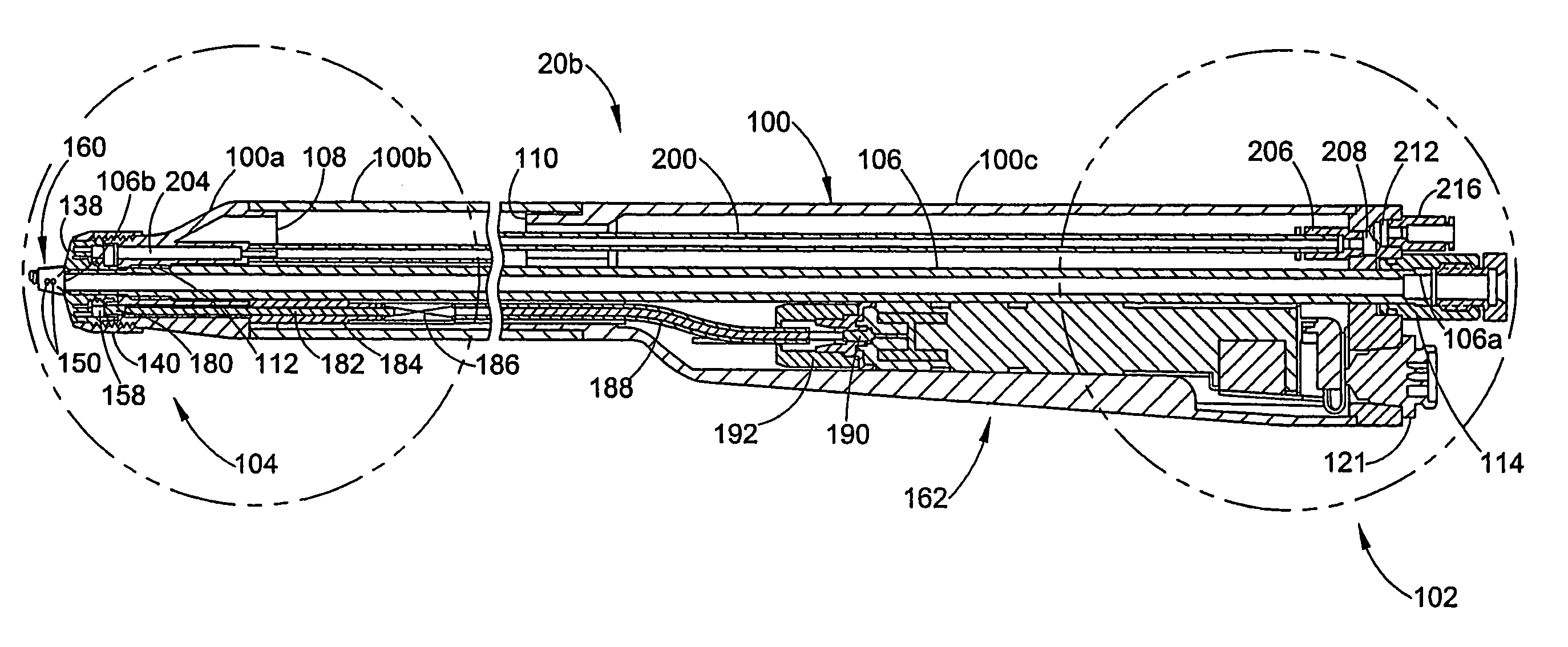
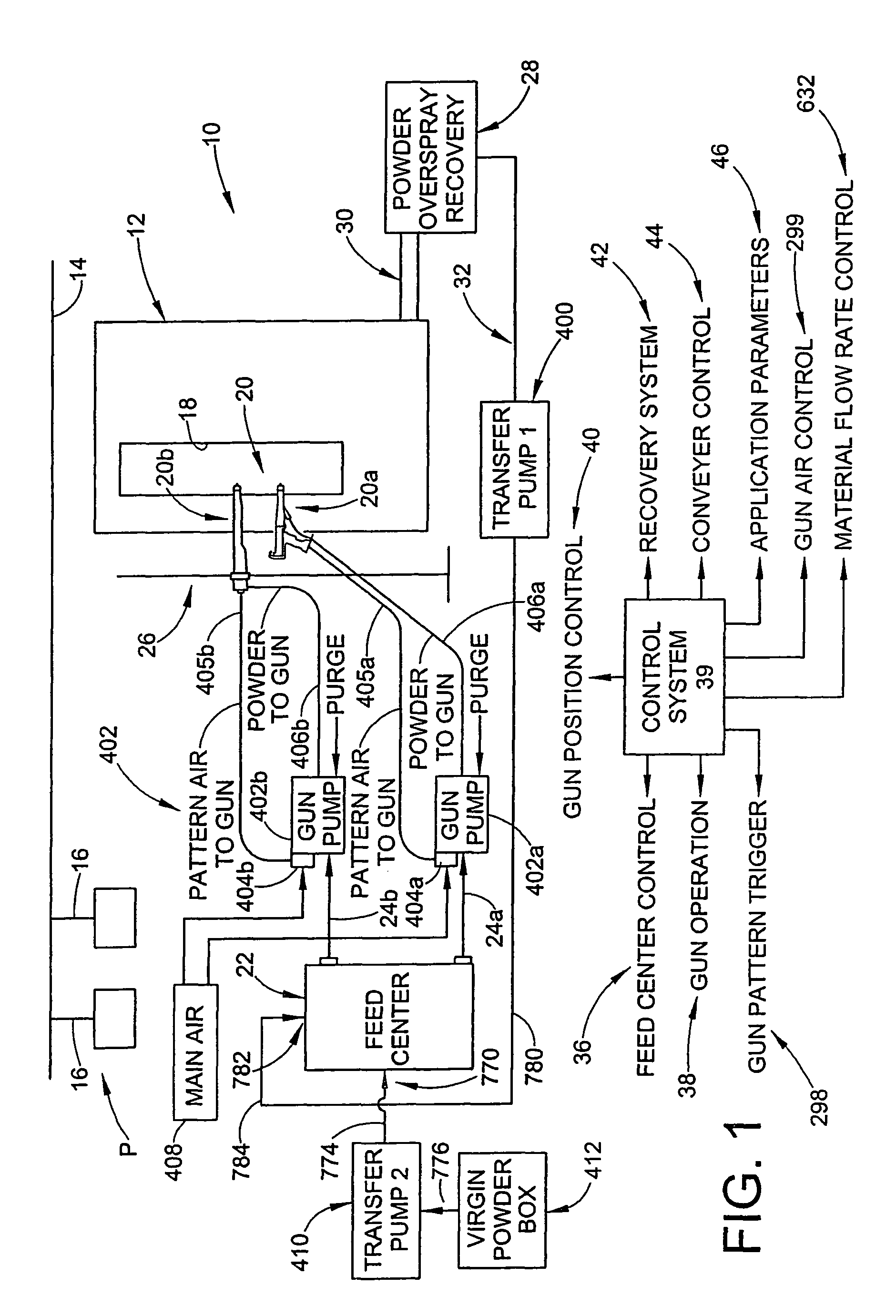
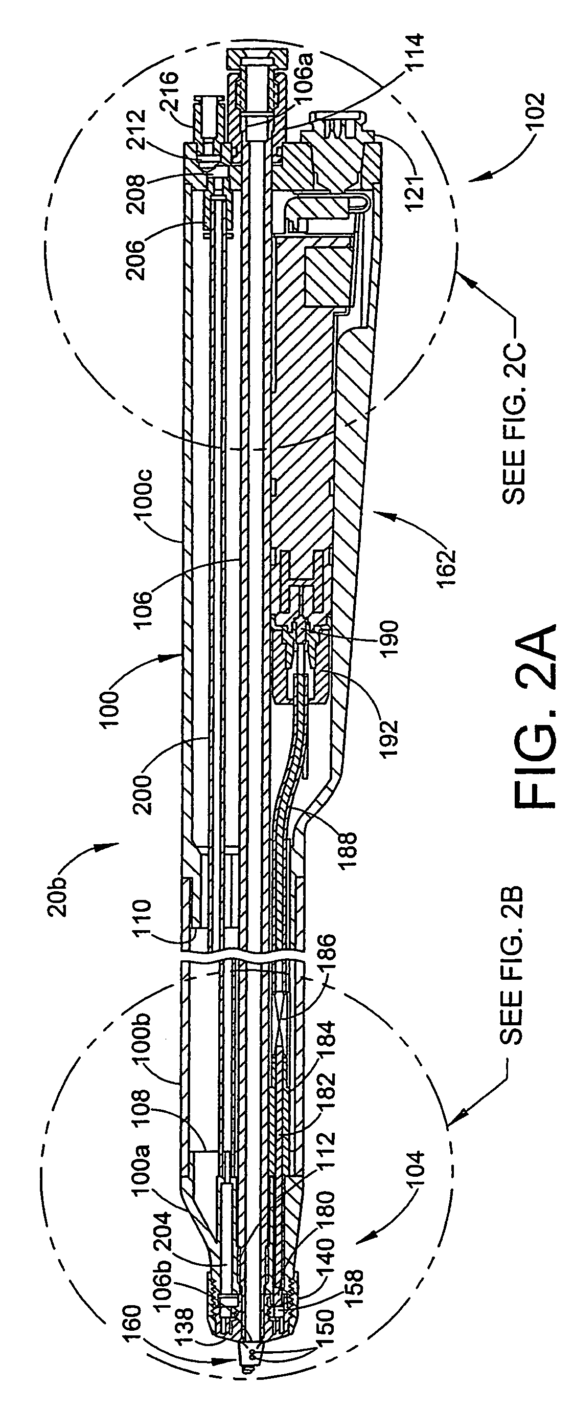
[0050]The invention contemplates a variety of new aspects for a particulate material application system. In general, the invention is directed to three major system functions, namely the supply of material, the applicator used to apply material to an object and a transfer device or pump for transferring powder from the supply to an applicator or from a recovery system to the supply. The three main system functions operationally interface with each other as well as other functions of a typical material application system, including an overspray containment function typically in the form of a spray booth and an overspray recovery function typically in the form of a filter based or cyclone based material recovery devices.

[0051]From a system perspective, the invention is directed among other things to improving the cleanability of the system so as to significantly reduce the total time needed for a color change operation. In addition, the invention is directed to various aspects that ma...


PUM


Abstract

A nozzle assembly for a material application device includes an expansion chamber for slowing down the velocity of powder fed to the nozzle from a dense phase pump. The nozzle assembly includes a nozzle insert that forms the expansion chamber and provides air assist function. The nozzle includes an integral deflector, and further includes a passageway for a charging electrode so that the electrical path is routed away from the powder path, while permitting the electrode tip to be centered in the powder spray pattern from the nozzle. The nozzle also includes air wash for the electrode. The nozzle outlet orifice has a cross-sectional area that is equal to or greater than the inlet cross-sectional area so that a slow moving dense phase powder cloud is produced by the nozzle.

Description

RELATED APPLICATIONS[0001]This application is a continuation in part of U.S. patent application Ser. No. 10 / 711,434 filed on Sep. 17, 2004 now abandoned for IMPROVED PARTICULATE MATERIAL APPLICATION SYSTEM, Ser. No. 10 / 515,400 filed on Apr. 29, 2005, now abandoned for SPRAY APPLICATOR FOR PARTICULATE MATTER and International application number PCT / US04 / 26887 filed on Aug. 18, 2004 for SPRAY APPLICATOR FOR PARTICULATE MATTER, and further by such continuations claims the benefit of U.S. provisional patent application Ser. Nos. 60 / 481,250 filed on Aug. 18, 2003, for POWDER APPLICATOR WITH PATTERN ADJUSTMENT; 60 / 523,012 filed on Nov. 18, 2003 for POWDER SPRAY APPLICATOR; 60 / 554,655 filed on Mar. 19, 2004 for POWDER COATING MATERIAL SPRAY GUN; and 60 / 524,459 filed Nov. 24, 2003 for PINCH PUMP WITH VACUUM TUBE, the entire disclosures all of which are fully incorporated herein by reference.TECHNICAL FIELD OF THE INVENTION[0002]The invention relates generally to material application systems...

Claims


Application Information

Patent Timeline
Patent Type & Authority Patents(United States)
IPC IPC(8): B05B5/00B05B5/03B05B5/16B05B7/00B05C5/00
CPCB05B7/1459B05B5/1683B05B5/032B05B12/002B05B15/025B05B12/14B05B15/55
Inventor MATHER, BRIAN D.BACHMAN, JAMES V.SCHROEDER, JOSEPH G.FULKERSON, TERRENCE M.TURNER, HERMAN E.
Owner NORDSON CORP
Why Eureka
Try Eureka