Optical arrangement for a flow cytometer

a flow cytometer and optical arrangement technology, applied in the direction of measuring devices, material analysis through optical means, instruments, etc., can solve the problems of short working distance of high na microscope lenses, limited physical space around samples and flow cells, and inability to arrange, etc., to achieve convenient separation

Active Publication Date: 2010-09-21
OJK CONSULTING
View PDF14 Cites 14 Cited by
  • Summary
  • Abstract
  • Description
  • Claims
  • Application Information

AI Technical Summary

Benefits of technology

[0018]Each sub-range can preferably be easily separated and sent to independent optical detectors. Furthermore, the means of separating each sub-range can be made operator adjustable to give the best performance for different

Problems solved by technology

For practical reasons, high NA microscope lenses have short working distances and limit the physical space around the sample and flow cell.
However, this arrangement is not practical when using a higher numerical aperture lens with a shorter working distance, as there is insufficient space around the flow cell for the incident laser beam.
Other optical desig

Method used


Image

  • Optical arrangement for a flow cytometer
  • Optical arrangement for a flow cytometer
  • Optical arrangement for a flow cytometer

Examples


Embodiment Construction

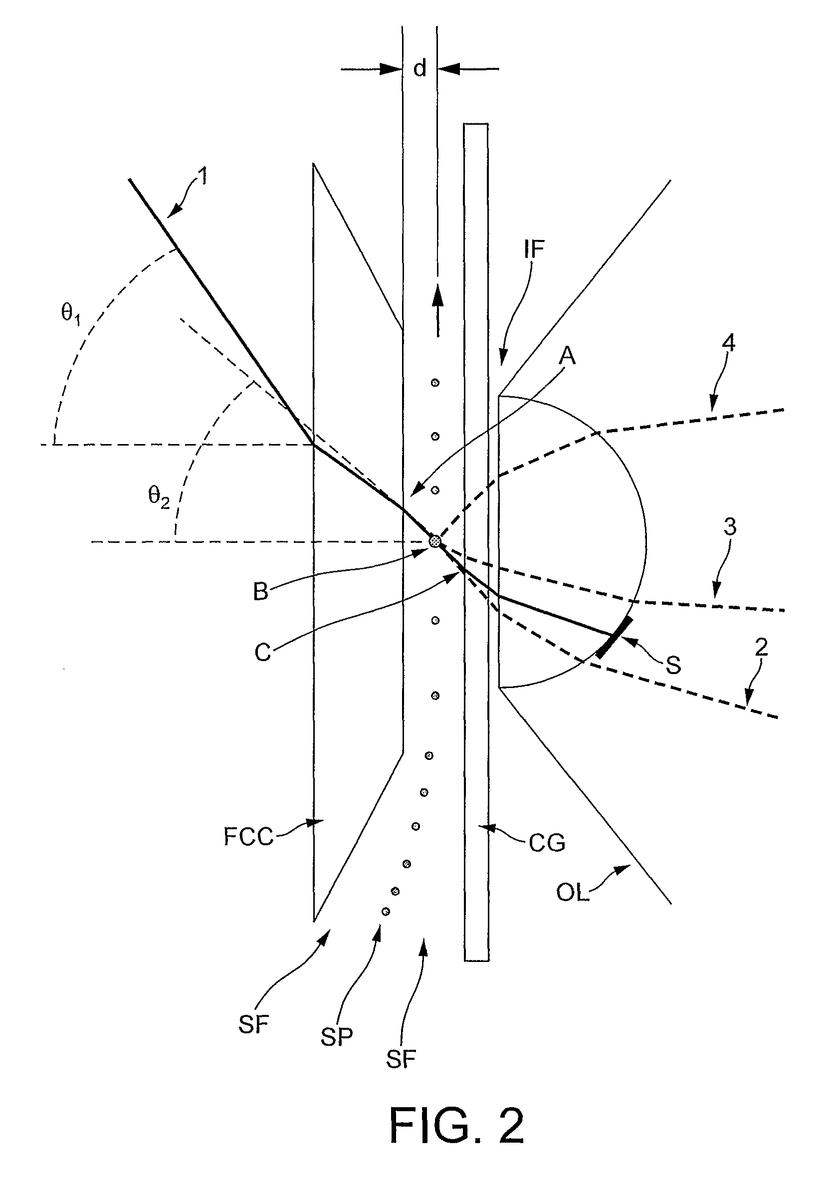
[0026]Let us define:[0027]‘Region B’ as being the volume of the sample stream which is illuminated by the radiation source.[0028]‘Region A’ as the area of intersection of the radiation beam with the flow cell wall closest to the radiation source.[0029]‘Region C’ as the area of intersection of the radiation beam with the flow cell wall furthest from the radiation source.

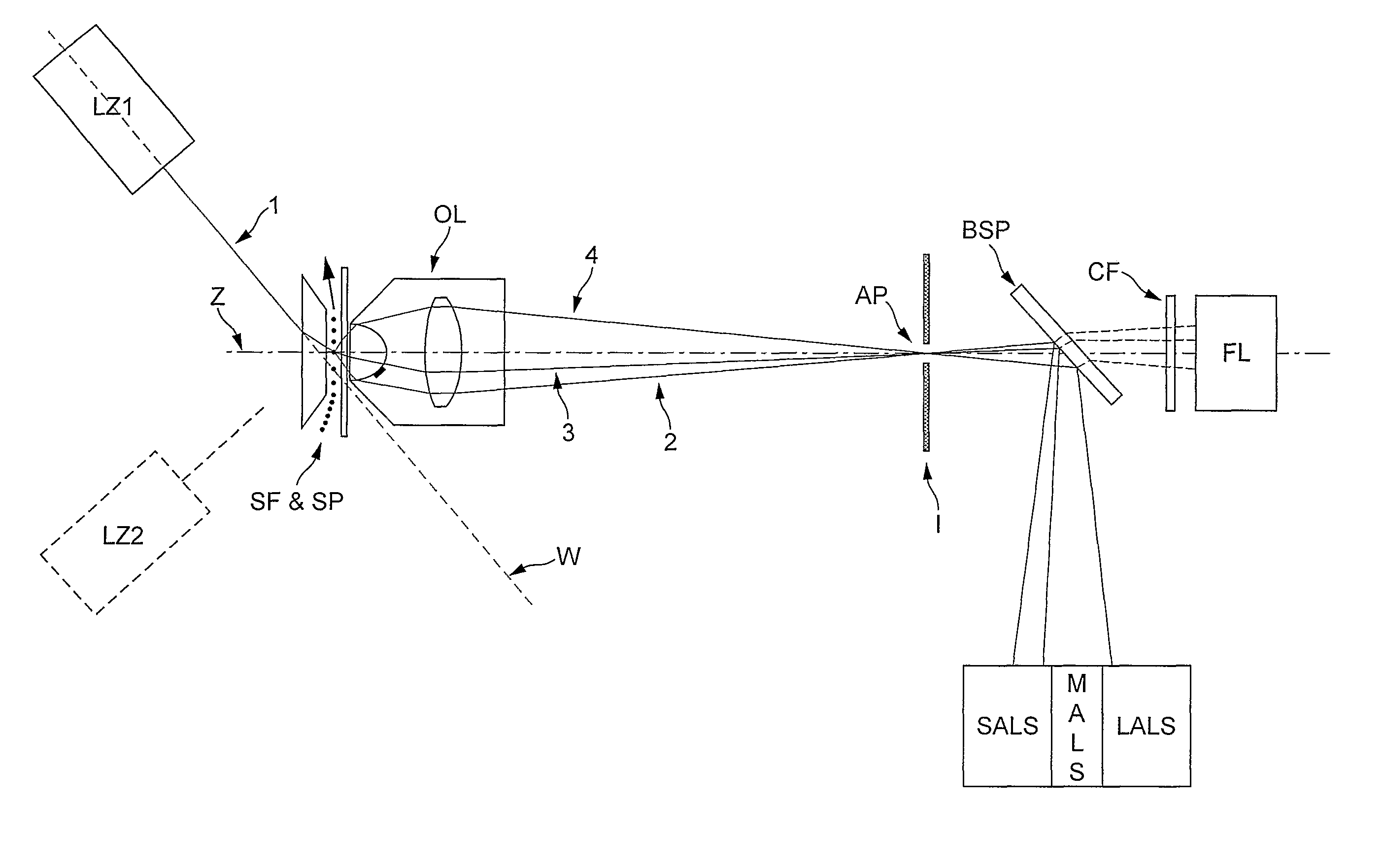
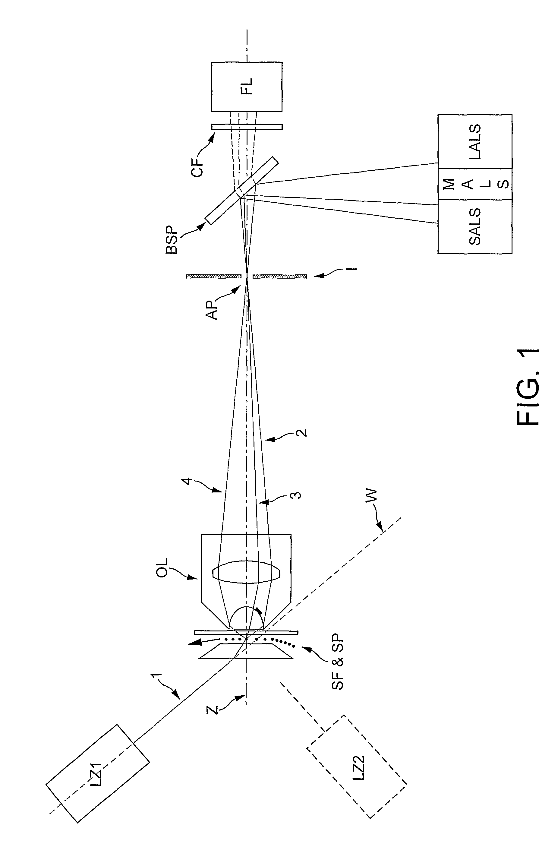
[0030]The present invention provides a novel and heretofore unobvious system for optically counting, measuring and differentiating particles such as bacteria, archaea, viruses and blood cells, as they travel through a flow cell. The system enables measurements of fluorescence and a wide range of light scatter angles to be taken from particles through a high numerical aperture lens. Furthermore the system achieves excellent spatial filtering of light from the measured particles through the use of a beam stop to reduce optical noise.

[0031]An optical system may provide:[0032]collection of a wide range of scattering angle...


PUM


Abstract

An optical system suited to high sensitivity measurement of small particles as they travel through a point of detection in a flow cell. The system consists of components along two optical axes, preferably but not necessarily, at approximately the Brewster angle to one another. The first axis incorporates a flow cell, high numerical aperture light collection lens, spatial filtering and optical detectors. The second axis incorporates a radiation source (typically a laser or arc-lamp) and beam shaping optics. The two axes are positioned at an angle sufficient to enable collection of small angle light scatter near the edge of the collection lens and to allow collection of medium and large angle light scatter through the centre and opposite side of the collection lens. The invention enables spatial filtering in the image plane of the collection lens to exclude radiation from the dominating sources of unwanted scattering in the flow cell, and also allows the use of a high numerical aperture lens to collect radiation scattered and fluoresced by the sample particles.

Description

CROSS-REFERENCE TO RELATED APPLICATION[0001]This application is a National Phase Patent Application of International Application Number PCT / GB2006 / 002304, filed on Jun. 23, 2006, which claims priority of British Patent Application Number 0 513 128.9, filed on Jun. 27, 2005.BACKGROUND OF THE INVENTION[0002]1. Field of the Invention[0003]This invention relates to particle measuring and counting apparatus, as incorporated into flow cytometers. The invention is particularly well suited to the measurement of small particles such as microspheres (typically 10 nm to 10 um diameter), cells (eg blood cells or bacteria), parts of cells (eg nuclei), or viruses.[0004]2. Description of Related Art[0005]A flow cytometer counts, measures and discriminates particles in a liquid by their optical properties as they flow through a beam of illuminating radiation one particle at a time. The radiation source is typically a laser and the machine is normally used to count and identify particles at rates up...

Claims


Application Information

Patent Timeline
IPC IPC(8): G01N21/00G01N15/14
CPCG01N15/14G01N2015/1452
Inventor KENYON, OLIVER
Owner OJK CONSULTING
Why Eureka
Try Eureka